Method for testing high-temperature breaking limit of antiskid brake control box

A technology of anti-skid brakes and control boxes, applied in electrical testing/monitoring, etc., to save test time and reduce energy consumption

Inactive Publication Date: 2013-09-11
XIAN AVIATION BRAKE TECH
View PDF3 Cites 23 Cited by
  • Summary
  • Abstract
  • Description
  • Claims
  • Application Information

AI Technical Summary

Problems solved by technology

[0024] c) The low-temperature step test needs to be completed under the condition that the cover is sealed. Since the required temperature change rate is very high per unit time, in order to make the cooling rate of the internal components of the aircraft anti-skid brake control box meet the test requirements, the reliability strengthening test box The heating rate within the test chamber needs to reach 60°C / min, but the general temperature test equipment cannot meet this requirement.

Method used


Image

  • Method for testing high-temperature breaking limit of antiskid brake control box
  • Method for testing high-temperature breaking limit of antiskid brake control box
  • Method for testing high-temperature breaking limit of antiskid brake control box

Examples


Embodiment 1

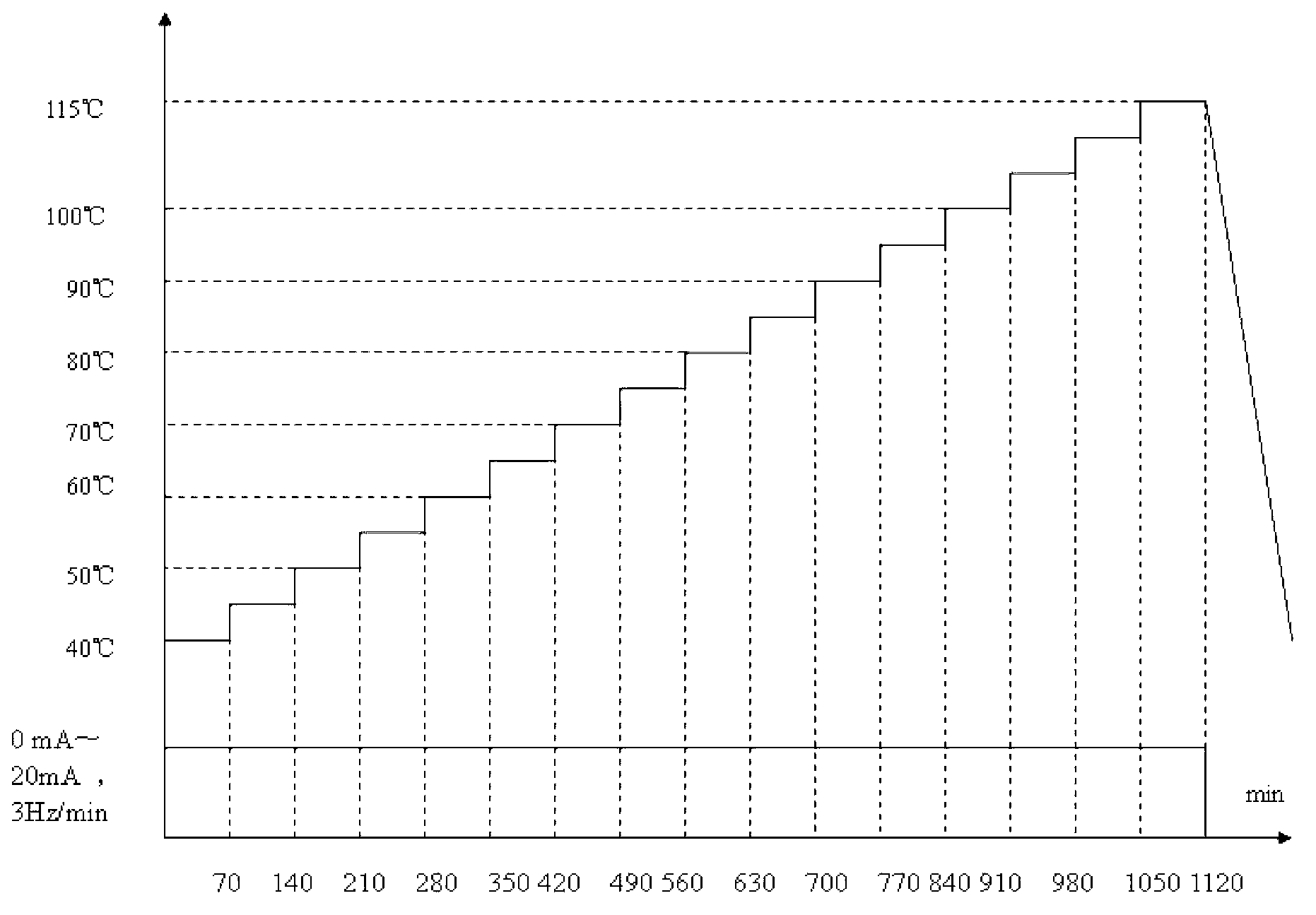
[0080] This embodiment is a high-temperature step-by-step test on the anti-skid brake control box of the first domestic regional aircraft brake system.

[0081] The concrete steps of this embodiment are:

[0082] Step 1, determine the test parameters

[0083] The high temperature step test parameters are suitable for three comprehensive test devices.

[0084]The test parameters include the starting point of the test temperature, the temperature rise step and rate, the holding time at each step, the working current and its application method, the required value of the high temperature damage limit and the number of test samples.

[0085] Determine the starting point of the test temperature. The starting point for this example is 40°C.

[0086] Determine the heating step size. In order to accurately determine the high-temperature damage limit value of the anti-skid brake control box, provide high-temperature damage data for the design of the anti-skid brake control box, and ...

Embodiment 2

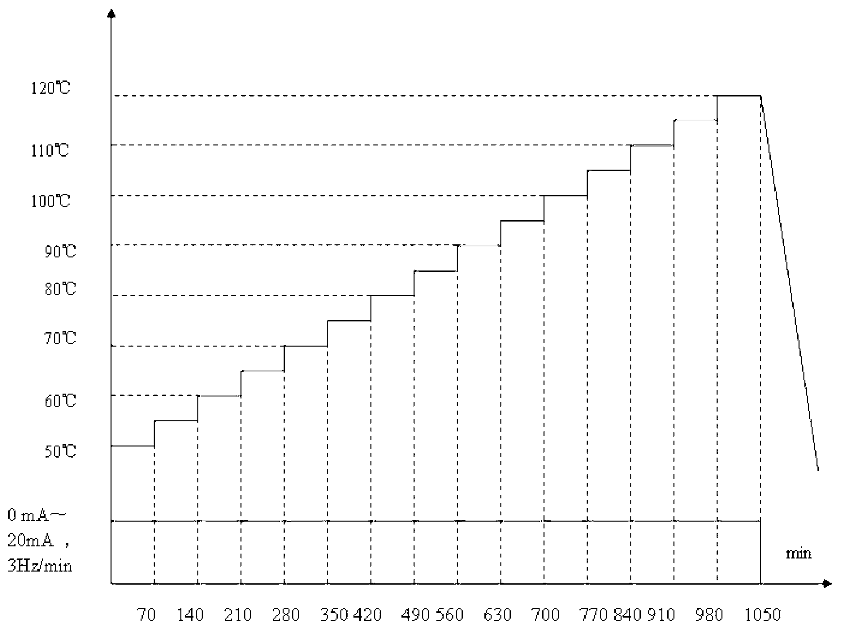
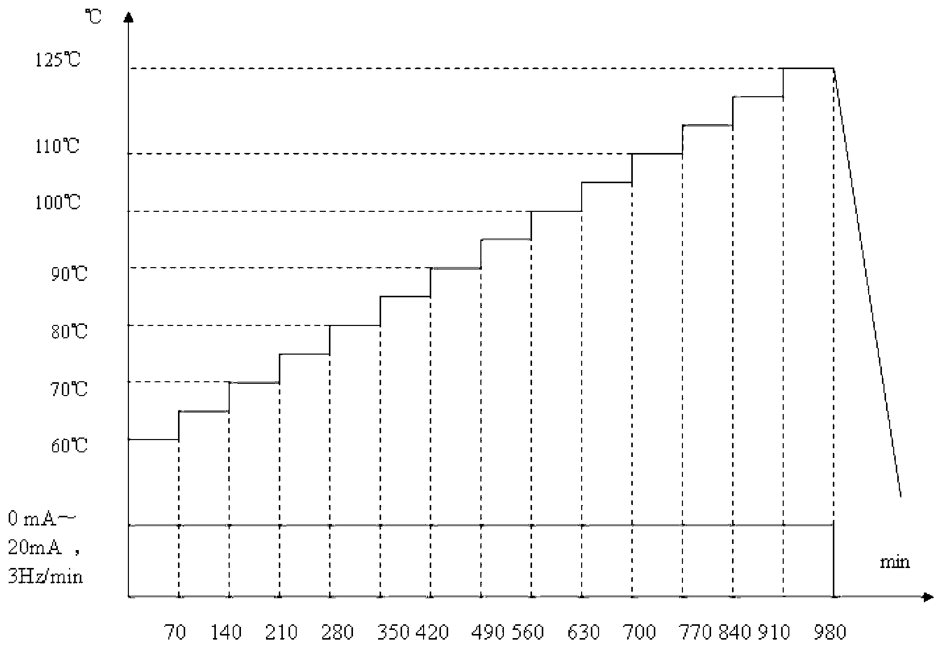
[0123] The processes of embodiment 2 and embodiment 3 all include determining the test parameters, testing the high temperature retention time of the anti-skid brake control box in the comprehensive environmental test chamber, formulating the high-temperature step test profile, testing the high-temperature damage limit and controlling the anti-skid brake after the improvement. Carry out each step of test verification, its specific process is the same as that of Example 1, the difference is that the test data in Example 2 and Example 3 are different from the test data of Example 1, as shown in Table 3 for details.

[0124] Table 3 Summary of main test data of hidden dangers of failure in step-by-step high-temperature stress test

[0125]


PUM


Abstract

Disclosed is a method for testing a high-temperature breaking limit of an antiskid brake control box. Three comprehensive testing devices are used for conducting a test, under a high-temperature stepping condition, antiskid brake working currents are applied, whether the performance of the antiskid brake control box is qualified or not is tested, if not qualified, improvement suggestions are put forward so that the high-temperature resistance of the antiskid brake control box can be improved, and if qualified, the test continues until required high-temperature resistance is achieved. A high-temperature stepping test belongs to accelerated life tests, test data of the high-temperature breaking limit are used as one of the bases for formulating the profile of a high-acceleration stress screening test. According to the method for testing the high-temperature breaking limit of the antiskid brake control box, the method with the high-temperature stepping test and the applied working currents integrated is used for stimulating high-temperature fault potential risks of the antiskid brake control box, the improvement suggestions directing at the fault potential risks are put forward and carried out, and the high-temperature breaking limit needed by the accelerated life tests and the high-acceleration stress screening profile is determined.

Description

technical field [0001] The invention relates to the field of electronic products of a transportation aircraft braking system, in particular to a method for testing high-temperature faults of an aircraft anti-skid brake control box by applying high-temperature step stress and working current. Background technique [0002] According to the international general standard GMW8287 "Highly Accelerated Life, Highly Accelerated Stress Screening", when determining the high temperature damage limit of electronic products, only step high temperature stress is applied, but no operating current is applied. [0003] The anti-skid brake control box is a product of the aircraft anti-skid brake system. It is designed with the functions of take-off line braking, anti-skid function during landing braking, grounding protection function during landing, and inter-wheel protection of left and right landing gear wheels during landing, etc. A variety of functions, any one of which does not meet the ...

Claims


Application Information

Patent Timeline
Patent Type & Authority Applications(China)
IPC IPC(8): G05B23/02
Inventor 乔建军郑卫东
Owner XIAN AVIATION BRAKE TECH
Why Eureka
Try Eureka