Azimuth device applicable to vehicular photoelectric turntable

A photoelectric turntable and azimuth technology, applied in non-electric variable control, position/direction control, instruments, etc., can solve the problems of larger device volume, larger size, and unrealized independent configuration of the rotary shaft system, etc., to achieve strong scalability , Improve the mechanical properties, improve the effect of maintainability

Active Publication Date: 2013-09-11
西安应用光学研究所
View PDF6 Cites 16 Cited by
  • Summary
  • Abstract
  • Description
  • Claims
  • Application Information

AI Technical Summary

Problems solved by technology

However, this device consists of a plurality of bearings to form a rotary shafting system. The outer support bearing is located at the upper end of the electromechanical components (torque motor and resolver). The independent configuration of the rotary shafting system is also not realized, and there is a problem that the bearing must be disassembled for maintenance of electromechanical components. ; In addition, the angular contact ball bearings, deep groove ball bearings, torque motors, resolvers and other electromechanical components in the device are installed on the inner and outer walls of the azimuth shaft, so that the selection of bearings and electromechanical components are related to each other, that is, the more the load of the azimuth device Larger, the larger the size of the angular contact ball bearing, the larger the size of the electromechanical components, resulting in a larger volume of the entire device

Method used


Image

  • Azimuth device applicable to vehicular photoelectric turntable
  • Azimuth device applicable to vehicular photoelectric turntable
  • Azimuth device applicable to vehicular photoelectric turntable

Examples


Embodiment Construction

[0023] The present invention will be described in detail below in conjunction with the accompanying drawings and preferred embodiments.

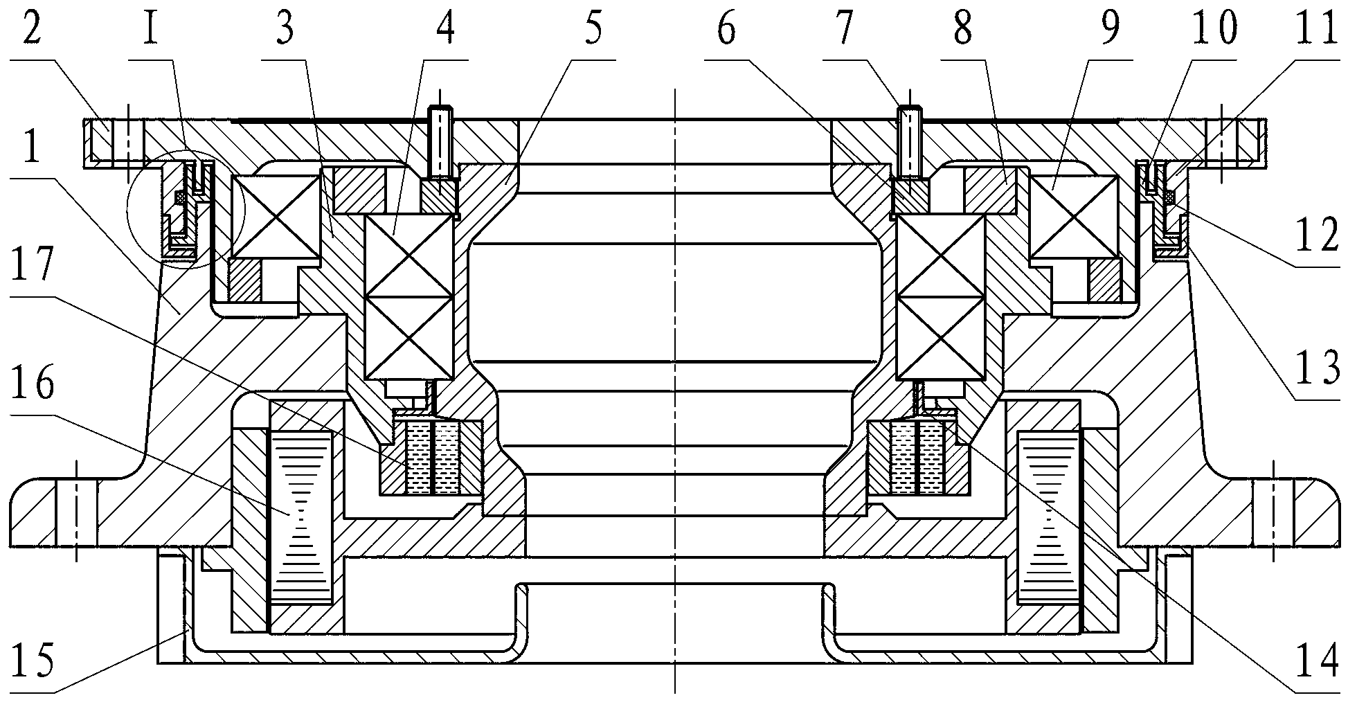
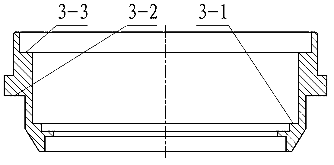
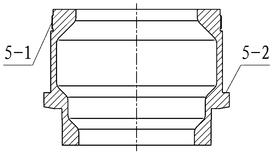
[0024] as figure 1 As shown, the azimuth device provided by the preferred embodiment of the present invention includes a rotary shaft system including an azimuth static shaft 3, an azimuth dynamic shaft 5, an azimuth adapter plate 2, a first bearing 4 and a second bearing 9, an azimuth housing 1, and a torque Motor 16, resolver 17 and azimuth bottom cover 15. The azimuth static shaft 3, the azimuth dynamic shaft 5, the azimuth adapter plate 2, the azimuth housing 1 and the azimuth bottom cover 15 all have a central through hole, and the central through hole is used to pass through the cables or install the signal at the upper and lower ends of the azimuth device. Conductive slip ring. Azimuth static axis 3 (see figure 2 ) is provided with an inner shaft shoulder 3-1 and an inner stepped surface 3-3 inside, and a ring-shaped outer boss 3-...


PUM


Abstract

The invention discloses an azimuth device applicable to a vehicular photoelectric turntable. The azimuth device comprises a revolving shaft system, an azimuth shell, a rotary transformer and a torque motor. The revolving shaft system comprises an azimuth dead shaft, an azimuth moving shaft, an azimuth rotating adaptor disc and two groups of bearings, the azimuth dead shaft is connected with the azimuth moving shaft and the azimuth rotating adaptor disc respectively via a first bearing and a second bearing, the first bearing bears biaxial loads, the second bearing is larger in diameter and bears radial and tipping loads, and thereby the rotating disc type revolving shaft system borne by the internal and external bearings is formed. The revolving shaft system as well as the rotary transformer and the torque motor are respectively positioned on an upper side and a lower side of an annular transverse plate in the middle of the azimuth shell and are independent to one another. Furthermore, a comprehensive labyrinth felt collar sealing structure is adopted. The azimuth device has the advantages of simple structure, low height, light weight, good maintainability, excellent expansibility, strong environmental suitability and the like, mechanical characteristics and capabilities of resisting shock, vibration and large-angle inclination of the photoelectric turntable are effectively improved, and tracking precision of photoelectric tracking equipment is guaranteed.

Description

technical field [0001] The invention belongs to the technical field of photoelectric tracking, and mainly relates to a photoelectric turntable, in particular to an azimuth device suitable for a vehicle-mounted photoelectric turntable. Background technique [0002] As a battlefield information perception and fire control system, photoelectric tracking equipment has been more and more widely used due to its unique characteristics. The photoelectric turntable is the core component of the photoelectric tracking equipment. Its basic structure is a set of two-axis precision servo turntable, which is used to carry photoelectric sensors such as TV cameras, infrared thermal imaging cameras and laser rangefinders, so as to realize the azimuth and pitch of the photoelectric tracking equipment. Target detection, acquisition and tracking. Most of the photoelectric turntables adopt the ground-level structure mode, that is, the elevation-azimuth (E-A) mode, in which the azimuth device is ...

Claims


Application Information

Patent Timeline
Patent Type & Authority Applications(China)
IPC IPC(8): G05D3/00
Inventor 马优恒高军王小齐瞿建荣胡博江涛崔海云赵振海孟海江邱亚李广良刘莹成莉
Owner 西安应用光学研究所
Why Eureka
Try Eureka