
Ultrasonic array probe signal acquisition component and preparation method thereof, and probe

An ultrasonic array and probe signal technology, which is applied in ultrasonic/acoustic/infrasonic diagnosis, acoustic diagnosis, infrasonic diagnosis, etc., can solve problems such as temperature rise of the probe, influence on the clarity of ultrasonic imaging, and smaller size of ultrasonic probe array elements, etc., to achieve Solve the effect of temperature rise

Active Publication Date: 2013-09-18
EDAN INSTR
View PDF10 Cites 39 Cited by
  • Summary
  • Abstract
  • Description
  • Claims
  • Application Information

AI Technical Summary

Problems solved by technology

In the existing ultrasonic array probes, in order to obtain more detailed scanning images, it is often necessary to set more ultrasonic probe array elements, which leads to a smaller size of a single ultrasonic probe array element, which can penetrate human tissue The ultrasonic signal is very weak; and the heat generated by the continuous excitation of the probe array vibration cannot be evacuated in time, resulting in local temperature rise inside and on the surface of the probe, affecting the comfort of the patient and adversely affecting the internal structure and performance of the probe; Or, the signal interference between the array elements of the ultrasound array probe has affected the further improvement of the clarity of ultrasound imaging

Method used


Image

  • Ultrasonic array probe signal acquisition component and preparation method thereof, and probe
  • Ultrasonic array probe signal acquisition component and preparation method thereof, and probe
  • Ultrasonic array probe signal acquisition component and preparation method thereof, and probe

Examples


Embodiment Construction

[0047] In order to make the object, technical solution and advantages of the present invention more clear, the present invention will be further described in detail below in conjunction with the accompanying drawings and embodiments. It should be understood that the specific embodiments described here are only used to explain the present invention, not to limit the present invention.

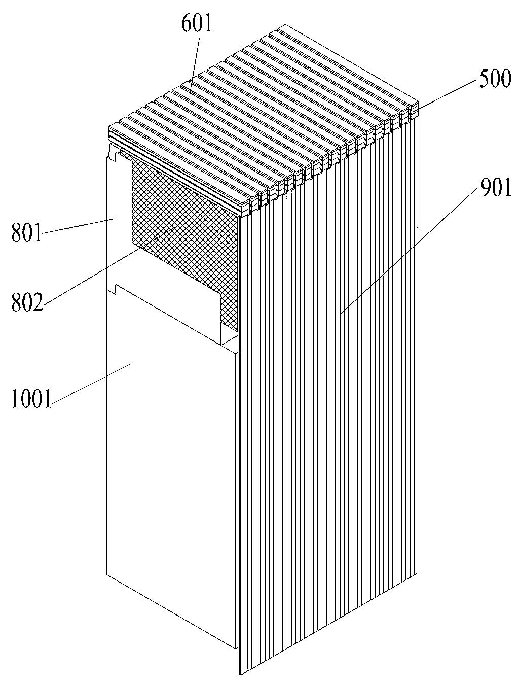
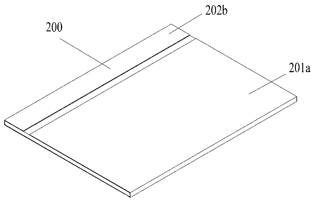
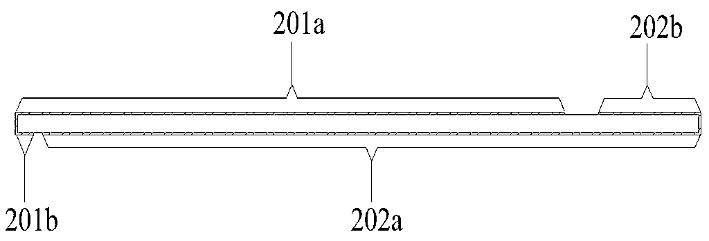
[0048] see Figure 1 to Figure 7 , the present invention is an ultrasonic array probe signal acquisition element, which is arranged inside the probe shell and connected to the probe circuit board and external cables, mainly including: two or more probe array elements arranged side by side, each probe array element Including: a backing 802 and a piezoelectric layer 500 composed of more than two piezoelectric wafers 200; the piezoelectric wafer is made of piezoelectric ceramics or piezoelectric single crystal;

[0049] One surface of each piezoelectric wafer 200 is provided with a positive electr...


PUM


Abstract

The invention relates to the technical field of ultrasonic probes, in particular to an ultrasonic array probe signal acquisition component and a preparation method thereof, and a probe. The acquisition component provided by the invention comprises two or more probe array elements, each probe array element comprises a backing and a piezoelectric layer composed of two or more piezoelectric crystal plates; flangings of positive electrodes and negative electrodes of the two piezoelectric crystal plates are butted; the piezoelectric layer is divided into a lead region, a heat conduction region and a signal region; a backing is connected to the signal region, and the bottom of the backing is connected with the bottom of the backing of an adjacent probe array element; a heat dissipating piece is connected to the heat conduction region, and the heat dissipating piece is connected with the ground electrode of an outer cable; and a flexible circuit board is connected with the lead region, and the flexible circuit board is connected with the outer cable through the probe circuit board. According to the ultrasonic array probe signal acquisition component and the probe provided by invention, the problem of probe temperature rising is effectively solved, the send-receive capacity of signals is improved, probe functions of testing image resolution ratio and sharpness are improved, and the impact of the probe array element signal crosstalk to imaging sharpness is decreased.

Description

Technical field [0001] The present invention involves the technology field of ultrasound probes, which specifically involves a kind of ultrasound probe signal collection element and a ultrasonic array probe, as well as a preparation method of an ultrasonic array probe signal collection element and a preparation method of an ultrasonic array probe. Background technique [0002] Ultrasonic array probe is an important component of ultrasonic diagnostic imaging equipment. The role of realization is to convert the electrical signal motivated by the host device into an ultrasonic signal to spread in the human soft tissue.The display of ultrasound images in the human body is displayed for doctors' analysis and diagnosis.In the existing ultrasonic array probe, in order to obtain more detailed scanning images, more ultrasonic probe arrays are often required, which leads to the size of a single ultrasonic probe array.The ultrasonic signal is very weak; and the heat generated by continuousl...

Claims


Application Information

Patent Timeline
IPC IPC(8): A61B8/00
Inventor 周丹罗华蔡文忠欧阳波
Owner EDAN INSTR
Learn More