Numerical control machining progressive interpolation method

An interpolation method and interpolation technology, applied in metal processing equipment, manufacturing tools, milling machine equipment details, etc., can solve the problems of over-burning of the surface structure of parts, low processing efficiency, tool wear, etc., and achieve large contact area and high processing efficiency. Low, small contact area effect

Inactive Publication Date: 2013-09-18
SHENYANG AIRCRAFT CORP
View PDF5 Cites 7 Cited by
  • Summary
  • Abstract
  • Description
  • Claims
  • Application Information

AI Technical Summary

Problems solved by technology

[0002] Traditionally, edge strips, ribs, and web parts of complex curved surfaces are processed by ball-end knife cutting. During the cutting process, the tool is always in contact with the processing surface in a local area, which results in serious wear of the local area of ​​the tool, making the tool The durability of the parts is greatly reduced; because the surface of the parts after line cutting generally needs to be polished and trimmed by the fitter, which increases the redundant workload, the most important thing is that the surface structure of the parts after polishing may be over-burned, which will affect the parts. surface quality and part life
[0003] Influenced by the traditional three-coordinate machining thinking, many curved surfaces are processed by three-coordinate line cutting or five-coordinate fixed swing angle line cutting. This type of processing method is widely used

Method used


Image

  • Numerical control machining progressive interpolation method
  • Numerical control machining progressive interpolation method

Examples


Example Embodiment

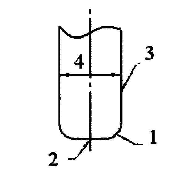
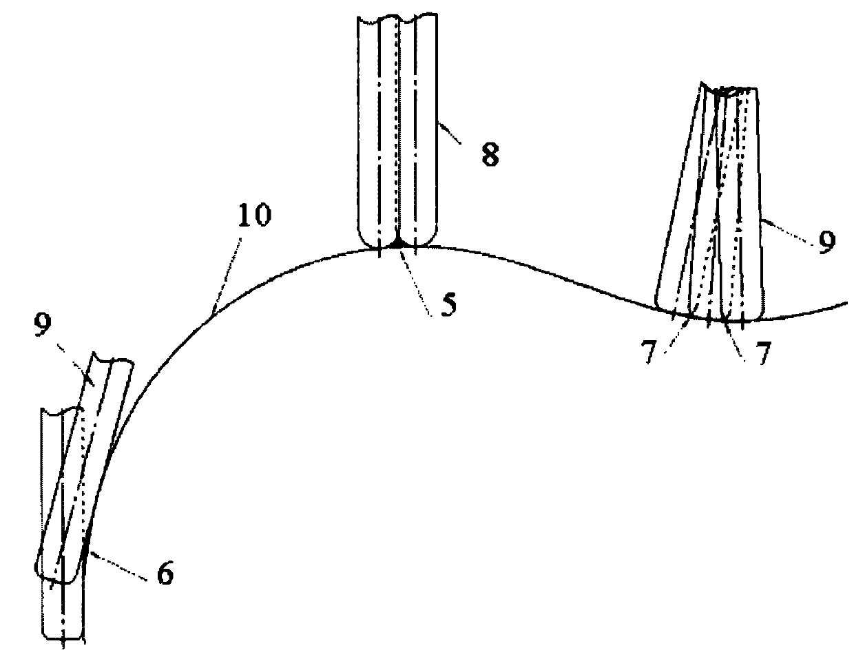
[0015] Attached below Figure 1~2 To further describe the present invention, in the figure: 1 is the bottom R of the tool, 2 is the bottom edge of the tool, 3 is the side edge of the tool, 4 is the diameter of the tool, 5 is the residual margin during line cutting, and 6 is the time of progressive interpolation of the side edge Residual margin, 7 is the residual margin when the bottom edge is progressively interpolated, 8 is the ball-end cutter, 9 is the CNC end mill, and 10 is the machined surface of the part.

[0016] The progressive interpolation method of NC machining is to make the tool axis direction parallel (or perpendicular) to the cutting point position of the curved surface during the processing, and use the processing tolerance of the curved surface to reasonably distribute the processing amount of the axial (or radial) layer to realize Envelope processing of curved surfaces; the contour of the curved surface processed by the progressive interpolation method of CNC...


PUM


Abstract

The invention provides a numerical control machining progressive interpolation method. A cutter for using is an end mill; the machining process comprises a side edge progressive interpolation process and a bottom edge progressive interpolation process. Compared with the row cutting and machining method of a traditional ball-end cutter, the bottom edge of a ball-end cutter and the machining surface are in contact, the numerical control machining progressive interpolation method has the characteristics of small contact area, low machining efficiency and the like. According to the numerical control machining progressive interpolation method provided by the invention, the side edge and the bottom edge of a commonly used end mill are in contact with the machining surface at the same time, the contact area is large, the efficiency is high, and the residual quantity is low.

Description

technical field [0001] The invention relates to the technical field of numerical control machining, in particular to a progressive interpolation method for numerical control machining. Background technique [0002] Traditionally, edge strips, ribs, and web parts of complex curved surfaces are processed by ball-end knife cutting. During the cutting process, the tool is always in contact with the processing surface in a local area, which results in serious wear of the local area of ​​the tool, making the tool The durability of the parts is greatly reduced; because the surface of the parts after line cutting generally needs to be polished and trimmed by the fitter, which increases the redundant workload, the most important thing is that the surface structure of the parts after polishing may be over-burned, which will affect the parts. Surface quality and part life. [0003] Affected by the traditional three-coordinate machining thinking, many curved surfaces are processed by t...

Claims


Application Information

Patent Timeline
IPC IPC(8): B23C3/00
Inventor 王德生钱深梅孙国雁
Owner SHENYANG AIRCRAFT CORP
Why Eureka
Try Eureka