a hybrid engine

A power machine and engine technology, applied in the direction of engine components, machines/engines, non-variable engines, etc., can solve the problems that inertia resistance and fluid resistance cannot be eliminated, the structure is not suitable for matching use, and the intensity of starting energy flow is reduced.

Active Publication Date: 2016-04-06
江苏锦明再生资源有限公司
View PDF13 Cites 0 Cited by
  • Summary
  • Abstract
  • Description
  • Claims
  • Application Information

AI Technical Summary

Problems solved by technology

However, the magnetic suspension bearing cannot eliminate the inertial resistance and fluid resistance when the engine starts, so the reduced starting energy flow intensity is limited
(2) Improve the structure of the working machinery to reduce resistance, such as changing the groove type of the generator from a straight groove type to an inclined groove type, but the effect is not very obvious
But this method is to use the electric energy of the grid, and cannot use other forms of energy
Another example: the Chinese patent application number is 201110357324.7. I applied for a multi-energy combined operation engine, which can realize the coordinated utilization of high-grade energy flow and low-grade energy flow, and achieve the purpose of complementary input and stable output. However, for low-grade The impeller driven by energy flow cannot pump and reduce the exhaust flow discharged by the traction engine driven by high-grade energy flow, so as to improve the efficiency of the traction engine
Another example: the Chinese patent application number is 201110381428.1, a fluid turbine engine that I applied for, can also realize the coordinated utilization of high-grade energy flow and low-grade energy flow, and achieve the purpose of complementary input and stable output, but its structure is not suitable for external use. Matching Use of Stator and Inner Rotor Motive Force Machine

Method used


Image

  • a hybrid engine
  • a hybrid engine
  • a hybrid engine

Examples


Embodiment Construction

[0034] The present invention will be further described below in conjunction with the accompanying drawings.

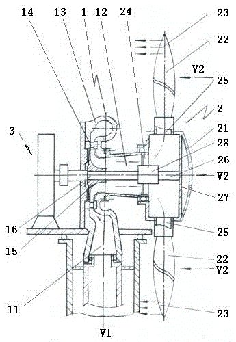
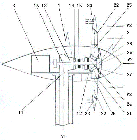
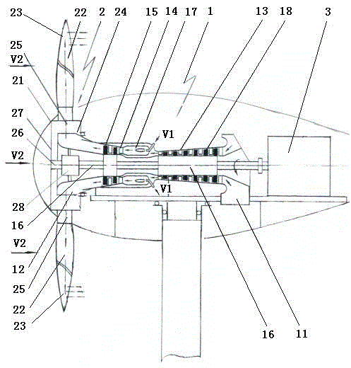
[0035] Such as figure 1 A kind of hybrid power machine shown is mainly composed of A type energy flow engine, B type energy flow engine and working machine 3 couplings, and said A type energy flow engine is composed of inlet port 11, discharge port 12, worm gear Outer stator and inner rotor expansion power machine 1 composed of shell 13, jet ring 14, impeller 15, impeller shaft 16, etc.; the type B energy flow engine is composed of hub 21 and hollow blades 22 installed around the hub 21 Horizontal shaft lift type impeller 2, the inner cavity of hollow blade 22 communicates with the inner cavity of hub 21, and the trailing edge portion 23 of hollow blade 22 is provided with a jet hole; the hub 21 is a hollow rigid shell with a Needed inflow hole 24, outflow hole 25 and installation hole, various components are assembled on the wheel hub for sealing installation; the di...


PUM


Abstract

The invention provides a hybrid power machine, which belongs to the field of fluid power machinery and is mainly formed by coupling an A-kind energy flux engine with a B-kind energy flux engine, wherein the A-kind energy flux engine utilizes pressure energy, kinetic energy and heat energy carried by fluid and is provided with a flow discharge port, the B-kind energy flux engine is formed by a wheel hub and hollow blades arranged at the periphery of the wheel hub, the inner cavities of the hollow blades are communicated with the inner cavity of the wheel hub, the rear marginal parts of the hollow blades are provided with jet-flow holes, the flow discharge port of the A-kind energy flux engine and a flow inlet port in the wheel hub of the B-kind energy flux engine are rotated to be coupled and are communicated, a system can not only effectively utilize the energy of low-grade energy flow but also utilize energy of other kinds and grades, so that the purpose of complementary importing and stable exporting is realized, and the hybrid power machine can be used for driving various working machines.

Description

technical field [0001] The invention relates to fluid and thermodynamic machinery, in particular to a hybrid power machinery capable of inputting multiple energy flows to realize stable output. Background technique [0002] All kinds of engines are the products of human social civilization, and they have become indispensable machinery for the development of today's society. Therefore, people have developed engines that utilize various energy sources. Engines of various structures mainly utilize thermal expansion energy, kinetic energy, potential energy, pressure energy, etc. of various energy sources. Of course, there are also electric motors that utilize electromagnetic energy. These engines can be roughly divided into the following two categories according to the type of energy they use: The first category is engines that use fossil energy, including various well-known internal combustion engines, steam turbines, jet turbines, etc. These are all heat engines and are based ...

Claims


Application Information

Patent Timeline
Patent Type & Authority Patents(China)
IPC IPC(8): F01D1/00F01D5/14F01D9/02
Inventor 王政玉王超颖张玉芹
Owner 江苏锦明再生资源有限公司
Why Eureka
Try Eureka