Heat exchanger of Stirling engine
A Stirling engine and heat exchanger technology, which is applied to machines/engines, hot gas variable capacity engine devices, mechanical equipment, etc., can solve the problems of low heat exchange efficiency, high manufacturing cost, and small heat exchange area, and achieves High heat exchange efficiency, solving the effect of small heat exchange area and uniform connection
- Summary
- Abstract
- Description
- Claims
- Application Information
AI Technical Summary
Problems solved by technology
Method used
Image

Examples
Embodiment 1
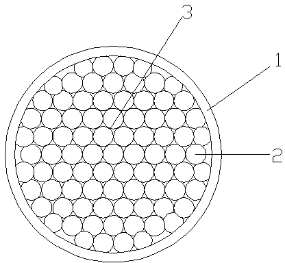
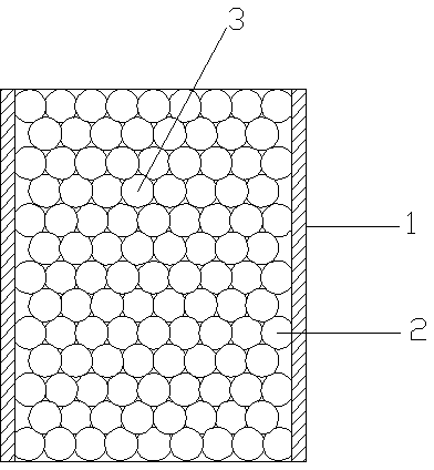
[0021] Embodiment 1: as figure 1 and figure 2 A Stirling engine heat exchanger shown includes a heat exchanger shell 1, the heat exchanger shell 1 has a cylindrical structure, and a spherical body 2 is arranged inside the heat exchanger shell 1, and the spherical body 2 fills the entire heat exchange Inside the shell 1, two spherical bodies 2 are connected to each other to form a heat exchanger body 3. The inner wall of the heat exchanger shell 1 is fixedly connected to the outer surface of the heat exchanger body 3. The spherical bodies 2 can be made of stainless steel or copper alloy. In this embodiment, it is made of stainless steel. The heat exchanger body 3 is formed by hot pressing of spherical bodies 2, that is, the shell of the heat exchanger is filled with spherical bodies, and then the two ends of the shell of the heat exchanger are pressed together by pressing plates. Put them together into a high-temperature furnace. The temperature of the high-temperature furnac...
Embodiment 2
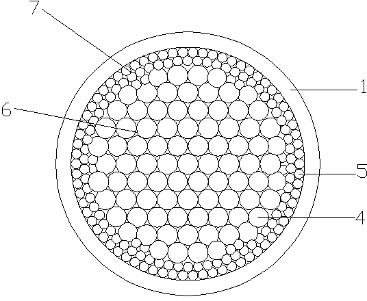
[0022] Embodiment 2: as image 3 and Figure 4 A Stirling engine heat exchanger shown includes a heat exchanger shell 1, the heat exchanger shell 1 has a cylindrical structure, and a spherical body 2 is arranged inside the heat exchanger shell 1, and the spherical body 2 fills the entire heat exchange Inside the shell 1, two spherical bodies 2 are in contact with each other to form a heat exchanger body 3. The inner wall of the heat exchanger shell 1 is fixedly connected to the outer surface of the heat exchanger body 3. The spherical bodies 2 include the first spherical body 4 and the outer surface of the heat exchanger body 3. The second spherical body 5, the radius of the first spherical body 4 is greater than the radius of the second spherical body 5, the heat exchanger body 3 includes the first heat exchanger body 6 and the second heat exchanger body 7, the first spherical body 4 is mutually Connected together to form the first heat exchanger body 6, the first heat excha...
Embodiment 3
[0023] Embodiment 3: as Figure 5 A Stirling engine heat exchanger shown includes a heat exchanger shell 1, the heat exchanger shell 1 has a cylindrical structure, and a spherical body 2 is arranged inside the heat exchanger shell 1, and the spherical body 2 fills the entire heat exchange Inside the shell 1, two spherical bodies 2 are in contact with each other to form a heat exchanger body 3. The inner wall of the heat exchanger shell 1 is fixedly connected to the outer surface of the heat exchanger body 3. The spherical bodies 2 include the first spherical body 4 and the outer surface of the heat exchanger body 3. The second spherical body 5, the radius of the first spherical body 4 is greater than the radius of the second spherical body 5, the heat exchanger body 3 includes the first heat exchanger body 6 and the second heat exchanger body 7, the first spherical body 4 is mutually Connected together to form the first heat exchanger body 6, the first heat exchanger body 6 ha...
PUM
 Abstract
Description
Claims
Application Information
 - R&D
- Intellectual Property
- Life Sciences
- Materials
- Tech Scout
- Unparalleled Data Quality
- Higher Quality Content
- 60% Fewer Hallucinations
Browse by: Latest US Patents, China's latest patents, Technical Efficacy Thesaurus, Application Domain, Technology Topic, Popular Technical Reports.
© 2025 PatSnap. All rights reserved.Legal|Privacy policy|Modern Slavery Act Transparency Statement|Sitemap|About US| Contact US: help@patsnap.com