Supercharge Your Innovation With Domain-Expert AI Agents!

Clutch device

A clutch device and clutch technology, applied in the direction of clutches, fluid-driven clutches, non-mechanical drive clutches, etc., can solve the problems of fuel efficiency or operating efficiency reduction, unstable operation state of internal combustion engines, and time-consuming problems, so as to improve ease of sale Good performance, operating efficiency or power consumption

Active Publication Date: 2013-09-18
HONDA MOTOR CO LTD
View PDF6 Cites 2 Cited by
  • Summary
  • Abstract
  • Description
  • Claims
  • Application Information

AI Technical Summary

Problems solved by technology

Therefore, it takes a long time to disengage the clutch, and the excessive rotation state of the internal combustion engine occurs, which may lower fuel efficiency or operating efficiency.
And, on the contrary, when the rotational speed of the internal combustion engine drops sharply and a shift operation is required, as described above, it takes a long time to disengage the clutch, so the rotational speed drops to an extremely low rotational speed region, and the operating state of the internal combustion engine may be unstable

Method used


Image

  • Clutch device
  • Clutch device
  • Clutch device

Examples


Embodiment Construction

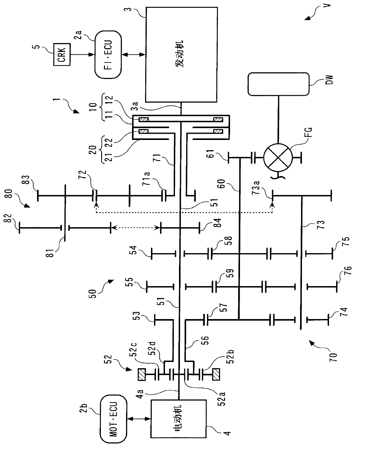
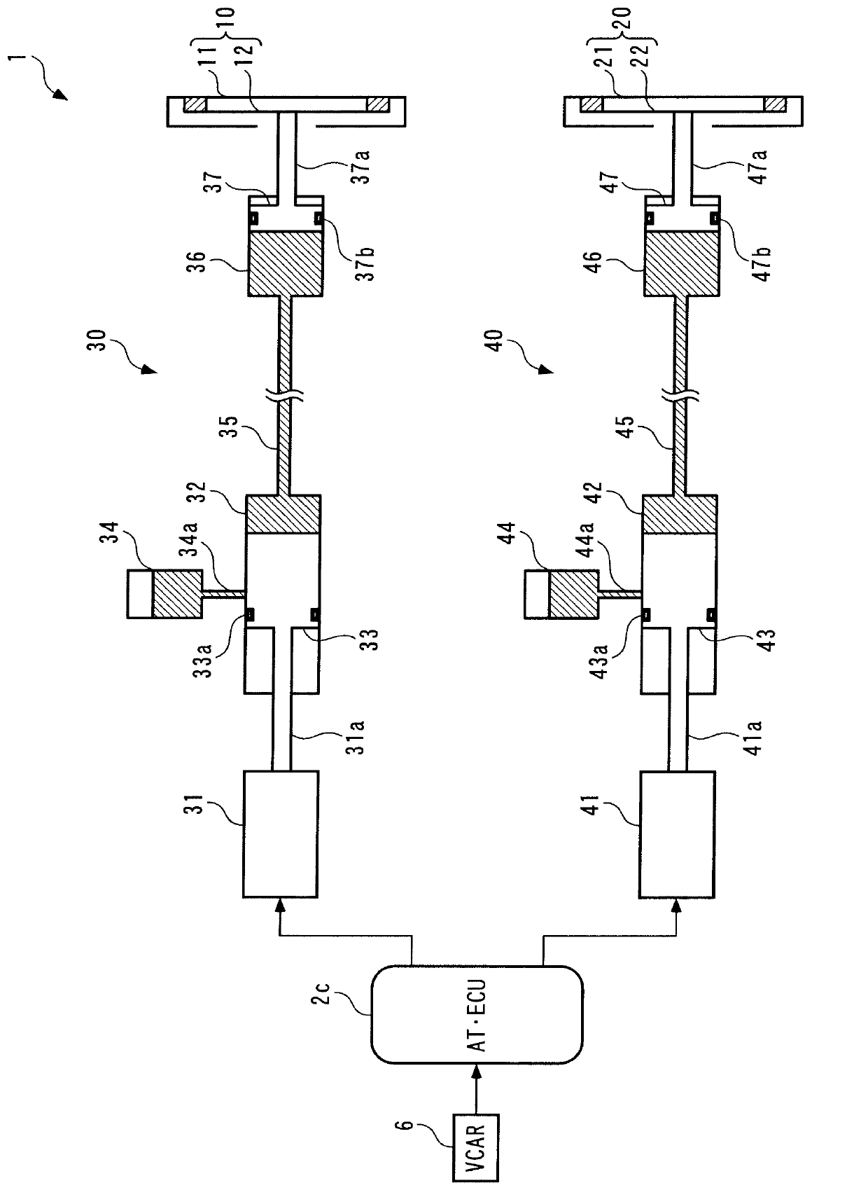
[0026] Next, a clutch device according to an embodiment of the present invention will be described with reference to the drawings. Such as figure 1As shown, the clutch device 1 of this embodiment is a clutch device applied to a drive system of a vehicle V. As shown in FIG. This vehicle V is a hybrid vehicle type vehicle, and has an internal combustion engine (hereinafter referred to as "engine") 3 as a prime mover, an electric motor (hereinafter referred to as "motor") 4, and a pair of drive wheels DW (only one is shown in the figure). , a pair of driven wheels DW (not shown), FI / ECU2a for engine control, MOT / ECU2b for motor control, AT / ECU2c for vehicle speed control (refer to figure 2 )Wait.

[0027] The engine 3 is a multi-cylinder gasoline engine type engine, and has a crankshaft 3a for outputting power. In the case of the engine 3, the operating state of the engine 3 is controlled by FI / ECU2a. The motor 4 is a brushless DC motor type motor, and its operating state i...


PUM


Abstract

The invention provides a clutch device. When a plurality of clutches respectively connects / disconnects a plurality of power transmission paths, a prime mover can be prevented from rotating at an extremely high or extremely low speed, thereby ensuring high operation efficiency and excellent operation performance of the prime mover. The clutch device comprises clutches, clutch drive devices and AT / ECU. When one of the clutches is driven to a connected state through one of the clutch drive devices, the AT / ECU calculates estimated rotating speed NE_END (step 3) at the responding time when the piston of the other clutch drive device is driven to a releasing position and returns to an off position. When the estimated rotating speed NE_END is not within the preset rotating speed area (NE_L(NE_END(NE_H), driving the piston of the other clutch drive device at a releasing position is prohibited.

Description

technical field [0001] The present invention relates to a clutch device having a plurality of clutches connected / disconnected according to hydraulic pressure. Background technique [0002] Conventionally, a clutch device described in Patent Document 1 has been known. The clutch device is a clutch device for a vehicle, and includes a clutch provided between an engine and a transmission, a clutch drive device for switching the on / off state of the clutch, a control device for controlling the clutch drive device, and the like. The clutch is composed of a clutch disc, a pressure plate and a diaphragm spring. [0003] Moreover, the clutch driving device has an active hydraulic cylinder, a slave hydraulic cylinder connected with the active hydraulic cylinder through an oil circuit, an electric actuator for driving the active piston in the active hydraulic cylinder, etc., and the active hydraulic cylinder, the oil circuit and the slave hydraulic cylinder The dynamic hydraulic cyli...

Claims


Application Information

Patent Timeline
IPC IPC(8): F16D25/10F16D48/06
Inventor 石川龙也
Owner HONDA MOTOR CO LTD
Features
  • R&D
  • Intellectual Property
  • Life Sciences
  • Materials
  • Tech Scout
  • Unparalleled Data Quality
  • Higher Quality Content
  • 60% Fewer Hallucinations
Learn More