Gas treating apparatus

A gas treatment and gas technology, applied in the field of gas decomposition and treatment devices, to achieve safe and reliable detoxification treatment effects

Active Publication Date: 2013-09-25
KANKEN TECHNO
View PDF5 Cites 10 Cited by
  • Summary
  • Abstract
  • Description
  • Claims
  • Application Information

AI Technical Summary

Problems solved by technology

In the aforementioned conventional pyrolysis type gas treatment device using atmospheric pressure plasma, the gas to be treated and combustion-supporting gas such as oxygen are mixed in a relatively close position in the reactor, so the combustion space has the following disadvantages: Danger: The so-called "backfire" that returns from the reactor to the upstream of the piping that supplies the gas to be processed

Method used


Image

  • Gas treating apparatus
  • Gas treating apparatus

Examples


Embodiment Construction

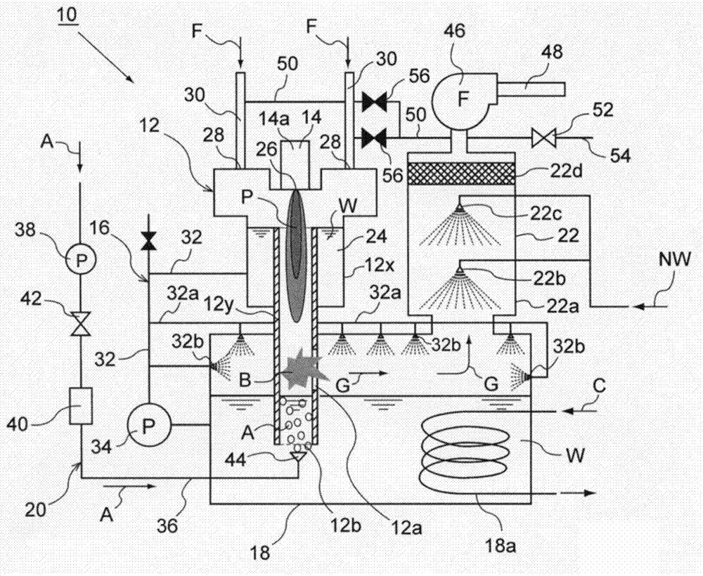
[0042] Hereinafter, the present invention will be described based on the illustrated embodiments. figure 1 It is a block diagram showing the outline of the gas processing apparatus 10 of this embodiment. As shown in the figure, the gas treatment device 10 of this embodiment is roughly composed of a reactor 12, a plasma generator 14, a water supply unit 16, a water tank 18, an oxidizing gas supply unit 20, a post-stage wet scrubber 22, and the like. In addition, this embodiment shows the case where the plasma generator 14 is used as a heat source, but the heat source used in the gas treatment device 10 is not limited to this device, and although not shown, a flame burner or an electric heater may also be used.

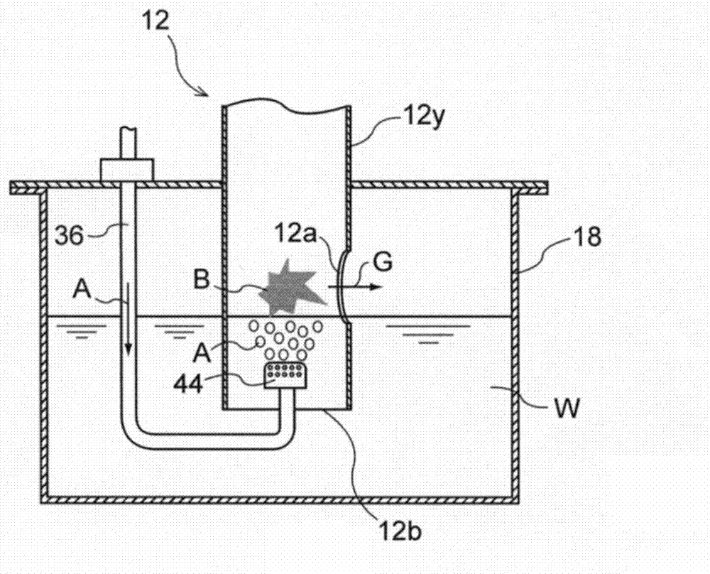
[0043] The reactor 12 is a device for enclosing the atmospheric pressure plasma P generated by the plasma generator 14 and the processing target gas F, and thermally decomposing the processing target gas F inside it. Layer pipe: a cylindrical outer cylinder 12x, whose ...


PUM


Abstract

The invention provides a gas treating apparatus. Hydrogen and other combustible gases with high concentrations flow into the apparatus, various gases are treated safely and reliably. According to the gas treating apparatus (10), gases (F) to be treated are supplied from the inlet (28) at the upper portion of the cylindrical reactor (12) vertically arranged on a water tank (18), thermal decomposition of the gases (F) to be treated is carried out in the reactor (12), and gases (G) to be discharged generated after thermal decomposition are discharged from the outlet (12a) arranged at the lower part of the relactor (12). The lower end surface of the relactor (12) is provided with an opening, the oxidizing gas (A) transmitted from water (W) in the water tank (18) is conducted to the reactor (12) through a lower opening (12b).

Description

technical field [0001] The present invention relates to a device for decomposing gases including gases harmful to the human body, greenhouse gases, ozone layer depleting gases, etc., especially gases discharged from the manufacturing process of semiconductors or liquid crystals. Background technique [0002] Currently, various industrial production processes for manufacturing or treating products have been developed and implemented, and there are many kinds of gases (hereinafter referred to as "processing target gases") discharged from such various industrial production processes. Therefore, it is necessary to appropriately use various gas treatment methods and gas treatment devices according to the type of treatment target gas discharged from the industrial production process. [0003] For example, taking one of the semiconductor manufacturing processes as an example, monosilane (SiH 4 ), chlorine, PFC (perfluorinated compounds) and other gases are used, and when the gas t...

Claims


Application Information

Patent Timeline
Patent Type & Authority Applications(China)
IPC IPC(8): B01D53/00B01D53/18F23G7/06
Inventor 加藤利明
Owner KANKEN TECHNO
Why Eureka
Try Eureka