Pulverized coal static separator with cambered blades

A static separation and blade technology, applied in the direction of solid separation, separating solids from solids with airflow, chemical instruments and methods, etc., can solve the problems of large blade wear, weak airflow, and difficult to filter large coal powder particles, etc. Achieve the effect of improving coal fineness, reasonable design and simple structure

Inactive Publication Date: 2013-09-25
HUADIAN ELECTRIC POWER SCI INST CO LTD
View PDF4 Cites 0 Cited by
  • Summary
  • Abstract
  • Description
  • Claims
  • Application Information

AI Technical Summary

Problems solved by technology

[0003] At present, there are also some other structures of coal dust static separators, such as the Chinese patent whose publication date is March 11, 2009, and whose publication number is CN101380631, which discloses a coal mill separator, which includes a motor , an inner cone, an outer cone and a cover body, the cone ends of the inner cone and the outer cone face downward, the inner cone is placed in the outer cone, and the cover covers the outer cone On the upper edge of the inner cone, static blades are arranged between the cover and the static blades are arranged longitudinally and arranged in a circle along the upper edge of the inner cone, and the static blades arranged in a circle There is a rotating impeller inside, and the rotating impeller is driven by the motor. The axes of the rotating impeller, the inner cone and the outer cone coincide. There is a discharge port above the rotating impeller, which makes it difficult to effectively increase the fineness of coal powder and reduce it effectively. wear on blades
Another example is that on April 25th, 2012, the publication date is CN202199508U, a Chinese patent that discloses a rotary coarse powder separator combined with static and movable blades. Including the separator shell, the shell is provided with a powder outlet pipe, a powder inlet pipe and a powder return pipe that communicate with the inside of the shell; the shell is provided with an inner cylinder, the upper end of the inner cylinder is open, and the lower end is communicated with the powder return pipe ; Between the upper end of the inner cylinder and the shell of the separator, there are a plurality of stationary blades arranged in a circle; a driving motor is installed on the shell, and the motor shaft passes through the upper shell of the separator vertically and enters the separator. inside the formed circle; the moving impeller rotor is connected to the motor shaft, and a plurality of moving blades are arranged on the moving impeller rotor in a circular arrangement; driven by the motor shaft, the moving impeller rotor drives the moving blades to rotate to form a static rotating separation area, and the static and moving blades are combined The structure of the type rotary coarse powder separator is complicated, it is difficult to effectively improve the fineness of coal powder, and it is difficult to effectively reduce the wear on the blades
[0004] The blades in the existing pulverized coal static separator are usually straight blade structures, the airflow generated is relatively weak, and the flow channel surrounded cannot make the airflow flowing through it form a certain rotation, and it is difficult to further filter large coal powder particles, coal powder Particles are more abrasive to blades

Method used


Image

  • Pulverized coal static separator with cambered blades
  • Pulverized coal static separator with cambered blades
  • Pulverized coal static separator with cambered blades

Examples


Embodiment 2

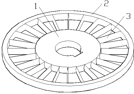
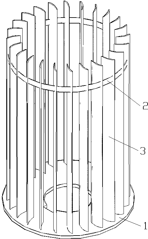
[0033] see figure 2 , Figure 4 to Figure 6 , the pulverized coal static separator using curved blades in this embodiment includes a rotating shaft disk 1, a ring 2 and several blades 3, and the pulverized coal static separator is a conical structure, wherein the center position of the rotating shaft disc 1 A shaft hole 11 is provided, and a shaft limiting opening 12 is provided on the edge of the shaft hole 11 .

[0034] The blade 3 in this embodiment is a curved surface structure, and the blade 3 is provided with a concave surface 31 and a convex surface 32. The concave surface 31 in the blade 3 is arc-shaped, and the convex surface 32 in the blade 3 is semi-elliptical. The two endpoints of the semi-ellipse coincide with the two endpoints of the semi-ellipse respectively, the line between the two endpoints of the semi-ellipse is the major axis of the ellipse, the length of the major axis of the ellipse is the chord length of the arc, and the ellipse The length of the mino...

Embodiment 3

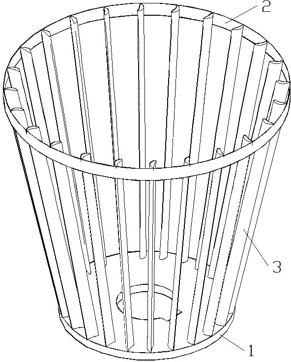
[0038] see Figure 3 to Figure 6 , the pulverized coal static separator using curved blades in this embodiment includes a rotating shaft disc 1, a ring 2 and several blades 3, and the pulverized coal static separator is a cylindrical structure, wherein the central position of the rotating shaft disc 1 A shaft hole 11 is provided, and a shaft limiting opening 12 is provided on the edge of the shaft hole 11 .

[0039] The blade 3 in this embodiment is a curved surface structure, and the blade 3 is provided with a concave surface 31 and a convex surface 32. The concave surface 31 in the blade 3 is arc-shaped, and the convex surface 32 in the blade 3 is semi-elliptical. The two endpoints of the semi-ellipse coincide with the two endpoints of the semi-ellipse respectively, the line between the two endpoints of the semi-ellipse is the major axis of the ellipse, the length of the major axis of the ellipse is the chord length of the arc, and the ellipse The length of the minor axis i...


PUM


Abstract

The invention relates to a pulverized coal static separator with cambered blades. The blades of an existing pulverized coal static separator are of a straight blade structure, airflow generated by the straight blades is weak and pulverized coal particles can heavily wears the blades. The pulverized coal static separator with the cambered blades comprises a rotation shaft round disk, a circular ring and a plurality of the cambered blades. The center of the rotation shaft round disk is provided with a rotation shaft hole, the rim of the rotation shaft hole is provided with a rotation shaft limit notch, and the blades are fixed onto the rotation shaft round disk and the circular ring. The pulverized coal static separator with the cambered blades is characterized in that every blade are of a cambered structure and provided with a convex surface and a concave surface, wherein the concave surface is in an arc shape and the convex surface is in a semiellipic shape, both ends of the arc shape and the both ends of the semiellipic shape are overlapped, the connection line between both ends of the semiellipic shape is the major axis of an ellipse, the length of the major axis is the chord length of the arc shape, and the length of the minor axis of the ellipse is six tenths of the radius of the arc. The pulverized coal static separator with the cambered blades is reasonable in design, can generate strong whirl airflow and can reduce the wear of the pulverized coal particles on the blades.

Description

technical field [0001] The invention relates to a pulverized coal static separator, in particular to a pulverized coal static separator with curved blades, which can be applied to static separators in industrial sectors where gas-solid two-phase separation is required. Background technique [0002] In all production processes accompanied by gas-solid two-phase, gas-solid separation is an indispensable link. has a wide range of applications. The working principles of the commonly used gas-solid separation devices are: gravity separation mechanism, inertial separation mechanism, centrifugal separation mechanism, and charge separation mechanism. The static and dynamic separators used for the separation of coarse and fine powder in coal mills in the power industry use the inertial separation mechanism to separate the coarse and fine powder. The coarse powder enters the coal mill for re-grinding, while the fine powder enters the furnace with the upward force of the primary wind....

Claims


Application Information

Patent Timeline
IPC IPC(8): B07B7/083
Inventor 孙科陈剑靳士奇
Owner HUADIAN ELECTRIC POWER SCI INST CO LTD
Why Eureka
Try Eureka