Novel composite floor system for super high-rise building

A composite floor and multi-storey building technology, which is applied in the direction of load-bearing elongated structural components, buildings, building components, etc., to achieve the effect of saving building space loss, reducing the amount of reinforcement and concrete, and improving comfort

Inactive Publication Date: 2013-09-25
CHINA CONSTR 4TH ENG BUREAU 6TH
View PDF6 Cites 2 Cited by
  • Summary
  • Abstract
  • Description
  • Claims
  • Application Information

AI Technical Summary

Problems solved by technology

Conventional reinforced concrete beams cannot meet the above requirements; a new beam-slab structure system is needed to meet the realistic requirements

Method used


Image

  • Novel composite floor system for super high-rise building
  • Novel composite floor system for super high-rise building
  • Novel composite floor system for super high-rise building

Examples


Embodiment 1

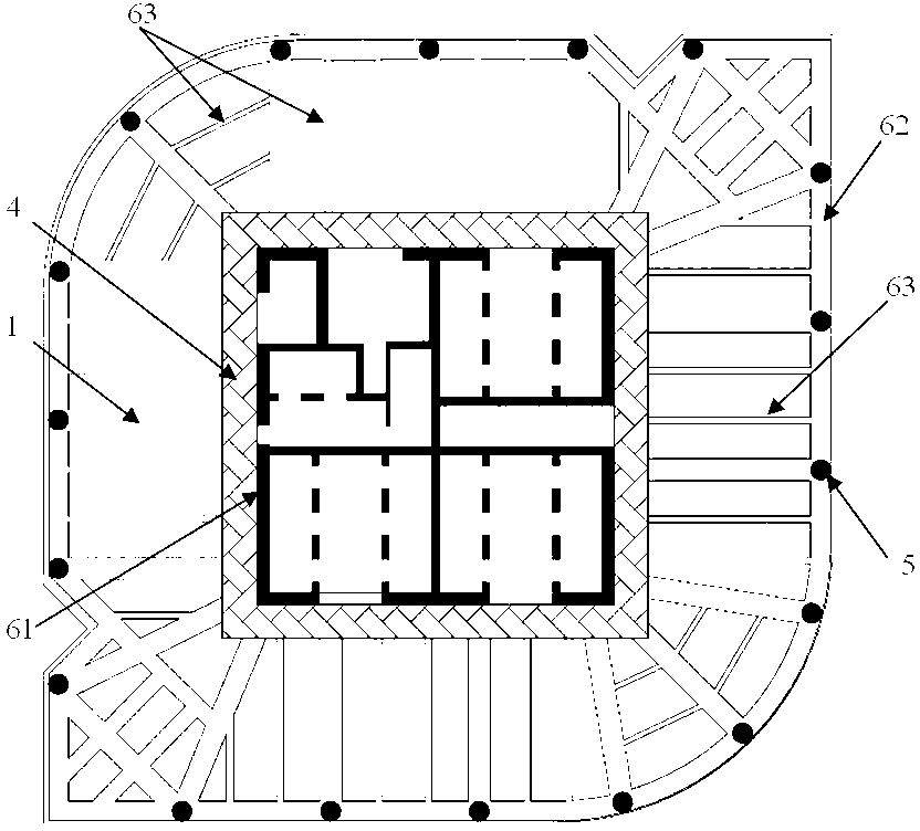
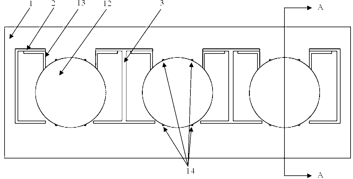
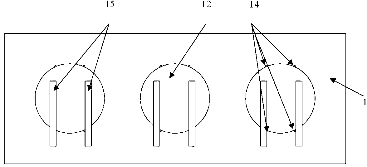
[0028] see figure 1 , a new type of composite floor system for super high-rise buildings, including an inner support wall 61, an outer support wall 62 and floor slabs, and steel tube concrete columns 5 are evenly distributed in the outer support wall 62, and each part of the surface of the super high-rise building The top of the storey is provided with an inter-story composite floor assembly; the inter-story composite floor assembly is composed of core tube wall cap 4 and beams, see Figure 8 and Figure 9 ,in,

[0029] The core tube wall cap 4 is a closed annular frame body, the thickness of the core tube wall cap 4 is between 450~300mm, the width of the core tube wall cap 4 is between 2000~3000mm, and the perimeter profile of the core tube wall cap 4 Match the outline of the supporting wall 61 in the building; the core tube wall cap 4 is constructed by steel bars; the top surface of the core tube wall cap 4 is connected with the ceiling of the floor, that is, the floor sl...

Embodiment 2

[0040] see figure 1 , a new type of composite floor system for super high-rise buildings, including an inner support wall 61 and an outer support wall 62, inside the outer support wall 62 there are uniformly distributed steel tube concrete columns 5, and on each floor of the super high-rise building surface There is an inter-story composite floor assembly on the top; the inter-story composite floor assembly is composed of core tube wall cap 4 and beams, see Figure 8 and Figure 9 ,in,

[0041] The core tube wall cap 4 is a closed annular frame body, the thickness of the core tube wall cap 4 is between 450~300mm, the width of the core tube wall cap 4 is between 2000~3000mm, and the perimeter profile of the core tube wall cap 4 Match the profile of the supporting wall 61 in the building; the top surface of the core tube wall cap 4 is connected with the ceiling of the floor, and the inner side of the core tube wall cap 4 is closely connected with the outer wall of the inner s...


PUM


Abstract

The invention provides a novel composite floor system for a super high-rise building and aims to overcome the defects that an existing high-rise building is small in span, large in self-weight, large in occupied space and the like. The novel composite floor system is characterized in that an interlayer composite floor system assembly is arranged on the top of each layer of the ground portion of the super high-rise building; each interlayer composite floor system assembly is composed of a core tube wall cap and a beam, wherein the core tube wall cap is a closed annular frame body; each beam is composed of a beam body and a wide and flat beam skeleton assembly. The novel composite floor system for the super high-rise building has the technological effects that the height of the beams in the novel composite floor system is only 8% to 15% of that of beams in a traditional technological structure, and therefore building space losses are saved; the usage amount of reinforcing bars and concrete in the beams is reduced due to the fact that hollow steel tubes are arranged internally, the self-weight of the structure is reduced, and structural stiffness is enhanced; in addition, due to the fact that the core tube wall caps and the beams are integrated, namely, the span of the beams is increased, therefore, labor and materials are saved, usable areas are increased, and firmness and durability of the building are improved.

Description

technical field [0001] The invention belongs to the technical field of buildings, and in particular relates to a novel composite floor system for super high-rise buildings in high-rise building construction. Background technique [0002] Frame-core tube structure is a commonly used structural type in high-rise buildings. It is a structural system composed of a core tube located in the middle of the building and a peripheral frame. The core tube is surrounded by an outer wall (shear wall) arranged in the center of the floor. It has a great ability to resist lateral force. The frame is arranged around the building. Generally, the column spacing is relatively large, which can provide a large space for the building. This structural form is also produced to meet the needs of the building. With the continuous improvement of the level of architectural design, high-rise buildings have higher requirements for floor clearance. While ensuring structural stability, how to effectively ex...

Claims


Application Information

Patent Timeline
Patent Type & Authority Applications(China)
IPC IPC(8): E04B1/00E04C3/293
Inventor 程群王理叶海龙蒋韶鑫管谈谈杨昱王成洋宋仕宽许战杨晓云
Owner CHINA CONSTR 4TH ENG BUREAU 6TH
Why Eureka
Try Eureka