Water-cooling dry-type slag discharge device of pulverized coal boiler

A technology for dry slag discharge and pulverized coal boilers, which is applied to lighting and heating equipment, etc., can solve the problems of extrusion broken slag not being able to meet the uniform discharge particle size and broken grate, so as to improve labor hygiene conditions, reduce emissions, The effect of saving the occupied land area

Active Publication Date: 2013-09-25
江苏靖隆合金钢机械制造有限公司
View PDF8 Cites 9 Cited by
  • Summary
  • Abstract
  • Description
  • Claims
  • Application Information

AI Technical Summary

Problems solved by technology

Extrusion broken slag cannot meet the requirement of uniform particle size, and when large piece...

Method used


Image

  • Water-cooling dry-type slag discharge device of pulverized coal boiler
  • Water-cooling dry-type slag discharge device of pulverized coal boiler
  • Water-cooling dry-type slag discharge device of pulverized coal boiler

Examples


Embodiment 1

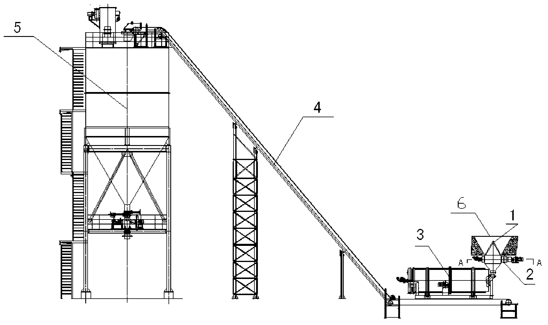
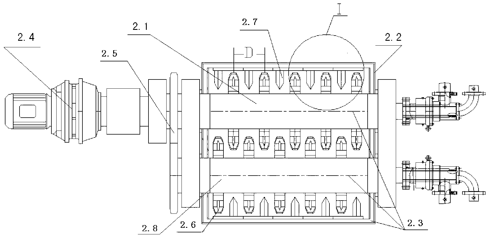
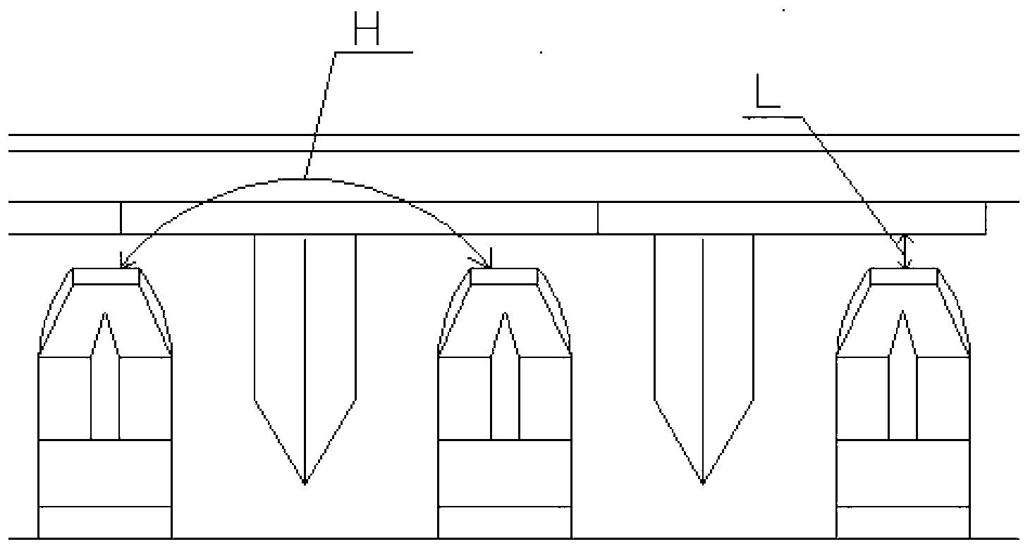
[0021] Such as figure 1 , 2 As shown, the pulverized coal boiler water-cooled dry slag discharge device provided by the present invention includes a drum slag cooler 3 and a slag conveying device 4 . The slag conveying device can be composed of a large-angle belt or a chain bucket conveyor. A slag crushing device is set between the boiler slag well 6 and the drum cooler 3. The slag crushing device provided in this embodiment is a high-temperature double-roller slag breaker 2. The outlet of the high-temperature double-roller slag breaker 2 is connected to the drum cooling The feed port of the slag machine 3 is connected, and the discharge port of the drum cold slag machine 3 is connected with the slag conveying device 4 . The high-temperature double-roller slag breaker includes two rotating rollers (2.1, 2, 8) driven by the transmission mechanism 2.4 to rotate in opposite directions. Several slag-breaking teeth 2.6 are arranged on the surface of the rotating rollers along the...

Embodiment 2

[0027] Such as Figure 5 As shown, when transforming the pulverized coal boiler system in use, it is necessary to determine the transformation plan according to the actual space on site. When the height is insufficient, a water-cooled spiral slag cooler 7 can be added between the high-temperature double-roller slag breaker 2 and the drum slag cooler 3 to increase the elevation of the cooled ash and carry out relay cooling.

[0028] Through the water-cooled dry-type slag discharge device for pulverized coal boilers provided by the present invention, the ash and slag can be broken into slag of <50mm, and the hot slag can be indirectly cooled by boiler feed water, and the heat can be recovered for reuse, and the temperature of the ash and slag can be lowered. To ≤100℃, in order to facilitate the use of inclined belt or chain bucket conveyor to transport to the slag bin for storage. Recycling the low-level heat energy lost by wet chilling can effectively avoid a large amount of w...


PUM


Abstract

The invention provides a water-cooling dry-type slag discharge device of a pulverized coal boiler. The water-cooling dry-type slag discharge device comprises a drum slag cooler and a slag conveyor, a slag crushing device is arranged between a boiler slag well and the drum slag cooler, an outlet of the slag crushing device is communicated with a feed port of the drum slag cooler, a discharge port of the drum slag cooler is communicated with the slag conveyor, the slag crushing device is a high-temperature double-roll slag crusher which comprises two rotary rolls driven to rotate oppositely by a transmission mechanism a plurality of slag crushing teeth are distributed on the surface of each rotary roll along the axial direction of the rotary roll, the rotary rolls are arranged in a water jacket case, and auxiliary slag crushing teeth corresponding to the slag crushing teeth on the surfaces of the rotary rolls are distributed on the inner wall face of the water jacket case. A cooling chamber for supplying cooling water is formed in each of the rotary rolls and the water jacket case to cool parts in contact with slag blocks. The water-cooling dry-type slag discharge device of the pulverized coal boiler can crush coal slag to the required size and store the crushed slag as well as achieve heat recycling.

Description

technical field [0001] The invention relates to a boiler slagging device using pulverized coal as fuel in industrial fields such as energy, metallurgy, and petrochemical industry, and in particular to a water-cooled dry slagging device for a pulverized coal boiler. Background technique [0002] At present, most of the slag discharge systems used in boiler systems fueled by pulverized coal in my country's energy, metallurgy, petrochemical and other industrial fields are wet slag discharge systems. There are also a few companies that use wire mesh conveyor belts and supporting scrapers together, and the cooling source uses air-cooled dry slag discharge systems. Although the two types of cold slag can cool the slag discharge temperature, there are many disadvantages. Both types of cold slag systems have serious defects such as excessive infrastructure investment, a large waste of recyclable resources, serious environmental pollution, and excessive floor space. . Wet slag disc...

Claims


Application Information

Patent Timeline
IPC IPC(8): F23J1/06
Inventor 陈亮
Owner 江苏靖隆合金钢机械制造有限公司
Why Eureka
Try Eureka