Head up display device based on laser holographic projection imaging

A head-up display device and laser holography technology, applied in the optical field, can solve the problems of high heat dissipation requirements of micro-reflectors, limiting the brightness of laser light sources, and irradiating human eyes, etc., to overcome the problem that the imaging distance cannot be adjusted at will and the structure of optical light path is simple , the effect of improving the utilization rate

Inactive Publication Date: 2013-09-25
JIANGSU INTELIGHT ELECTRONICS TECH
View PDF6 Cites 42 Cited by
  • Summary
  • Abstract
  • Description
  • Claims
  • Application Information

AI Technical Summary

Problems solved by technology

Since the laser light source is directly on the only micro-mirror, the heat dissipation requirements for the micro-mirror are very high, which greatly limits the brightness of the laser light source.
Since the micro-mirror has been in the process of high-speed flipping, and there is only one piece, very high requirements are placed on its reliability and stability. Once a problem occurs, the directly reflected laser light may directly irradiate the human eye, thereby causing human injury

Method used


Image

  • Head up display device based on laser holographic projection imaging
  • Head up display device based on laser holographic projection imaging
  • Head up display device based on laser holographic projection imaging

Examples


Embodiment 1

[0027] In order to clearly describe the implementation process of the present invention, the vehicle-mounted head-up display device is taken as an example below.

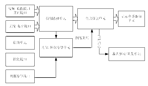
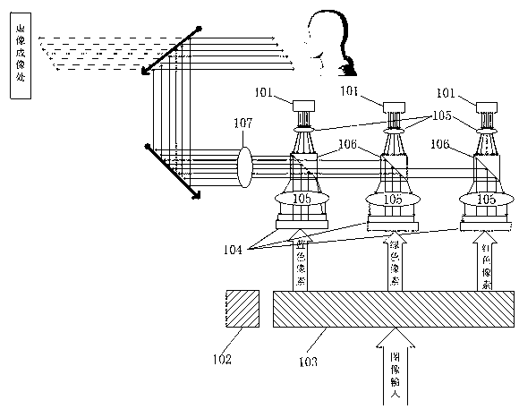
[0028] Such as figure 1 As shown, the light source uses three monochromatic light sources of red, green and blue to obtain a color image, and the spatial light modulation module uses three pieces of display media LCOS.

[0029] The vehicle-mounted head-up display device receives vehicle-related status information through the communication interface, such as vehicle speed, direction, engine speed, fuel volume, tire pressure, etc. through the vehicle interface; and navigation-related information through the interface with the navigation equipment, such as the road ahead , speed limit, signal lights, etc.; it can also communicate with portable devices through the wireless interface to receive related content to be displayed, such as Bluetooth, WIFI, infrared receiving mobile phone call information, etc. After receivin...

Embodiment 2

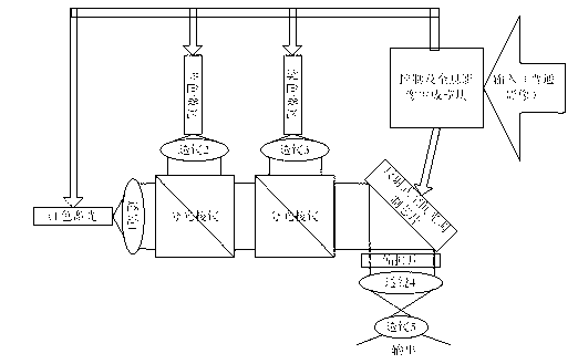
[0035] Such as image 3 As shown, the spatial light modulation module uses a display medium LCOS to realize the display of red, green and blue. The picture is displayed through the display medium in time-sharing, and is diffracted. The light source uses three kinds of monochromatic lasers: red, green and blue. 2 and 3 are light source correction lenses, so that the corresponding light source is converted from a non-plane wave to a plane wave. The lenses 4 and 5 form a reverse telescope structure for amplifying the holographic image output by the spatial light modulation module. The spatial light modulation module uses LCOS to add polarizers to realize phase modulation of light. The control module uses DSP to realize the function of synchronously converting the input ordinary image into a hologram image in real time, and synchronize the output of the light source and the hologram image. Compared with 3 pieces of display media, the brightness of this application will be reduc...


PUM


Abstract

The invention discloses a head up display device based on laser holographic projection imaging, and the head up display device based on laser holographic projection imaging belongs to the field of auxiliary display. The head up display device based on laser holographic projection imaging mainly comprises a light source system, an image processing system, a spatial light modulation module and an optical light path system. First, the image processing system receives to-be-displayed content through a data interface and transforms the content into a hologram form through a hologram conversion algorithm, or selects the to-be-displayed hologram stored in the system to perform simple arithmetic processing according to external inputted information, or directly outputs and displays on the spatial light modulation module; second, one (monochromatic) or a plurality of (chromatic) laser beams are emitted on the spatial light modulation module, and an original image is formed through diffraction in front of the spatial light modulation module; and last, the optical light path system is used for magnifying the imaged restored through diffraction to increase the field angle of the image. The head up display device based on laser holographic projection imaging can realize real-time dynamic adjustment of imaging distance, and the brightness of the displayed content can be changed in real time according to the ratio of the projection content area to the total projection area.

Description

technical field [0001] The invention relates to optical technologies such as holographic projection and laser diffraction, in particular to a method and device for realizing head-up display based on laser holographic projection imaging technology. Background technique [0002] Head Up Display (HUD) refers to an auxiliary display device that observers can see the required image information without looking down. [0003] The predecessor of the head-up display device is the optical sight used on fighter jets. This sight uses the principle of optical reflection to project the ring-shaped aiming circle light net on a piece of glass or the cockpit cover installed at the front of the cockpit. The projected image The focal length of the naked eye is set at an infinite distance, so that when the pilot aims at the target, it will not hinder the operation of the eyes and maintain a clear display. Head-up display technology was first applied to flight aids on aircraft. Head-up displays...

Claims


Application Information

Patent Timeline
Patent Type & Authority Applications(China)
IPC IPC(8): G02B27/01G03B21/00H04N5/74H04N9/31
Inventor 陈泉泉谈顺毅
Owner JIANGSU INTELIGHT ELECTRONICS TECH
Why Eureka
Try Eureka