Redox flowing method of vanadium redox flow galvanic pile and galvanic pile

A technology of liquid flow electricity and vanadium liquid, which is applied in the field of vanadium batteries, can solve the problems of unstable electrical performance of the stack, reduced flow rate of the liquid outlet, and voltage drop, etc., to provide electrical performance and stability, improve the overall electrical performance, Even effect of circulation and distribution

Active Publication Date: 2013-09-25
TIANJIN BINHAI ENERGY STORAGE TECH
View PDF3 Cites 2 Cited by
  • Summary
  • Abstract
  • Description
  • Claims
  • Application Information

AI Technical Summary

Problems solved by technology

[0003] The defect of the prior art is that when the entire vanadium redox flow battery stack adopts a set of positive-valence vanadium liquid circulation channels and a set of negative-valence vanadium liquid flow channels from top to bottom, the flow conductance of the vanadium liquid inside the entire stack is very poor. Evenly, the flow rate at the liquid inlet of the vanadium liquid is often very fast, and gradually the flow rate at the liquid outlet of the vanadium liquid will be greatly reduced, which will make the electrical properties of the entire stack very unstable and cause voltage drops. In order to solve For this problem, some companies also use pressurization to increase the flow rate of the vanadium liquid flow inside the stack, so as to improve the flow distribution of the vanadium liquid flow inside the stack, and increase the flow rate of the vanadium liquid flow at the liquid outlet at the end of the stack. Flow rate, after adopting this pressurized treatment method, the distribution uniformity of the vanadium liquid flow will be slightly better, but it still cannot solve the problem that the vanadium liquid inlet and outlet parts are as uniform as possible, and the entire vanadium liquid The tightness of the galvano stack is even worse, and there will be problems of liquid leakage and / or stringing. Once such leakage and / or stringing problems occur, it will have a very large impact on the entire vanadium flow stack. It may even lead to the scrapping of the entire vanadium liquid flow stack

Method used


Image

  • Redox flowing method of vanadium redox flow galvanic pile and galvanic pile
  • Redox flowing method of vanadium redox flow galvanic pile and galvanic pile
  • Redox flowing method of vanadium redox flow galvanic pile and galvanic pile

Examples


Embodiment Construction

[0017] The present invention will be further described below in conjunction with accompanying drawing.

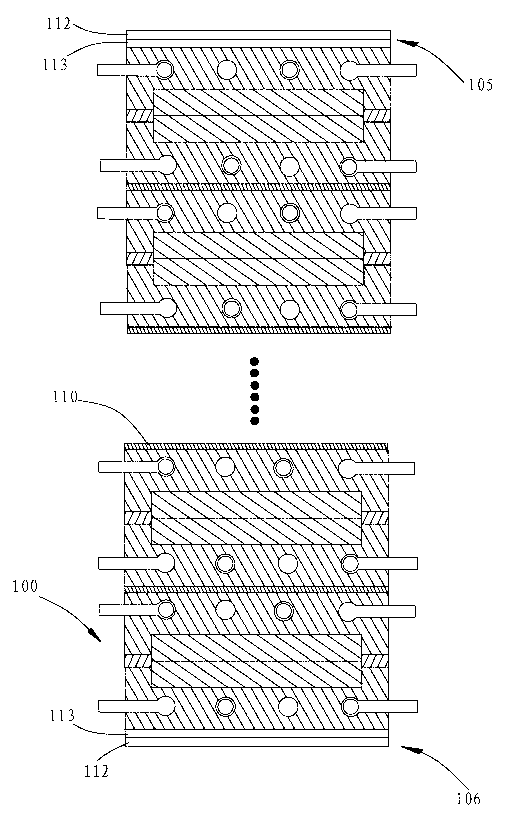
[0018] The invention provides a liquid flow method of a vanadium liquid flow stack. The liquid flow method of the vanadium liquid flow stack uses each stack unit in the vanadium liquid flow stack as an independent vanadium liquid circulation system.

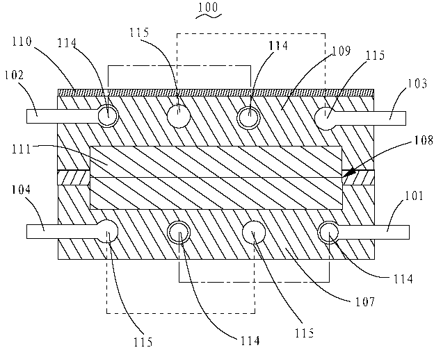
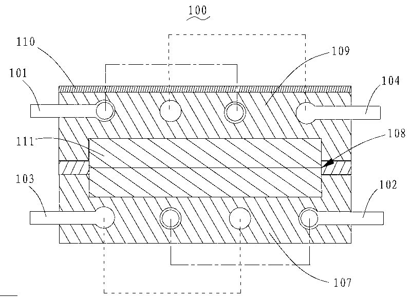
[0019] Specifically, the liquid inlet 101 of the positive vanadium liquid and the liquid outlet 104 of the negative vanadium liquid are set on the first working surface of each stack unit 100, and the second working surface of the stack unit 100 is set The liquid outlet 102 of the positive vanadium liquid and the liquid inlet 103 of the negative vanadium liquid, the liquid inlet 101 of the positive vanadium liquid is connected with the liquid outlet 102 of the positive vanadium liquid through the first flow channel, so The liquid inlet 103 of the negative vanadium liquid is connected with the liquid outlet 104 of the negative ...


PUM

PropertyMeasurementUnit
thicknessaaaaaaaaaa
thicknessaaaaaaaaaa

Abstract

The invention relates to a redox flowing method of a vanadium redox flow galvanic pile and the galvanic pile. The redox flowing method of the vanadium redox flow galvanic pile is characterized in that each galvanic pile unit in the vanadium redox flow galvanic pile is taken as an independent vanadium redox circulating system. The galvanic pile comprises a plurality of galvanic pile units, and each galvanic pile unit is provided with the independent vanadium redox circulating system. After the technical scheme is adopted, vanadium redox is more uniform in circulation and distribution inside the galvanic pile, so that the whole electric performance and stability of the whole vanadium galvanic pile are greatly improved; each galvanic pile unit independently operates, so that the sealing effect is better.

Description

【Technical field】 [0001] The invention relates to the field of vanadium batteries, in particular to a liquid flow method for a vanadium redox flow battery stack and a vanadium redox flow stack using the above liquid flow method. 【Background technique】 [0002] At present, the vanadium redox flow battery stack in the prior art includes a lower base plate, a lower end plate, a lower copper plate, a plurality of vanadium redox flow stack units, an upper copper plate, an upper end plate and an upper base plate stacked in sequence, wherein the vanadium liquid flow The stack unit further includes a lower frame plate, a carbon felt composite conductive plate, an upper frame plate and an ion membrane. In the stack unit, the thickness of the lower frame plate and the upper frame plate are controlled below 10mm, mostly 8mm. A set of positive vanadium liquid flow channels and a set of negative vanadium liquid flow channels are provided in the entire vanadium redox flow battery stack, a...

Claims


Application Information

Patent Timeline
Patent Type & Authority Applications(China)
IPC IPC(8): H01M8/18H01M8/04H01M8/24H01M8/02
CPCY02E60/50
Inventor 郑役军郑东冬
Owner TIANJIN BINHAI ENERGY STORAGE TECH
Why Eureka
Try Eureka