
FPGA encoding method and system and control method for unmanned aerial vehicle image transmission device

A transmission device and encoding system technology, applied in the field of high-resolution image encoding, can solve the problems of increased difficulty in implementation, high requirements for image compression and encoding transmission bandwidth, and the inability of the ground flight monitoring center to obtain relevant visual information on the scene in real time, so as to achieve real-time Good performance, enhanced real-time effect

Active Publication Date: 2013-09-25
NAT SPACE SCI CENT CAS
View PDF3 Cites 16 Cited by
  • Summary
  • Abstract
  • Description
  • Claims
  • Application Information

AI Technical Summary

Problems solved by technology

[0003] For the two technical solutions, the shortcomings of the former are more obvious. Due to the non-real-time transmission of images, the ground flight monitoring center cannot obtain the relevant visual information on the scene in real time. The live image can only be seen after landing, and it may be too late to react at this time
Although the latter has better real-time performance, it also has higher requirements for image compression coding and transmission bandwidth, and the difficulty of technical implementation also increases accordingly.

Method used


Image

  • FPGA encoding method and system and control method for unmanned aerial vehicle image transmission device
  • FPGA encoding method and system and control method for unmanned aerial vehicle image transmission device
  • FPGA encoding method and system and control method for unmanned aerial vehicle image transmission device

Examples


Embodiment Construction

[0053] The present invention will be further described below in conjunction with the accompanying drawings and specific embodiments.

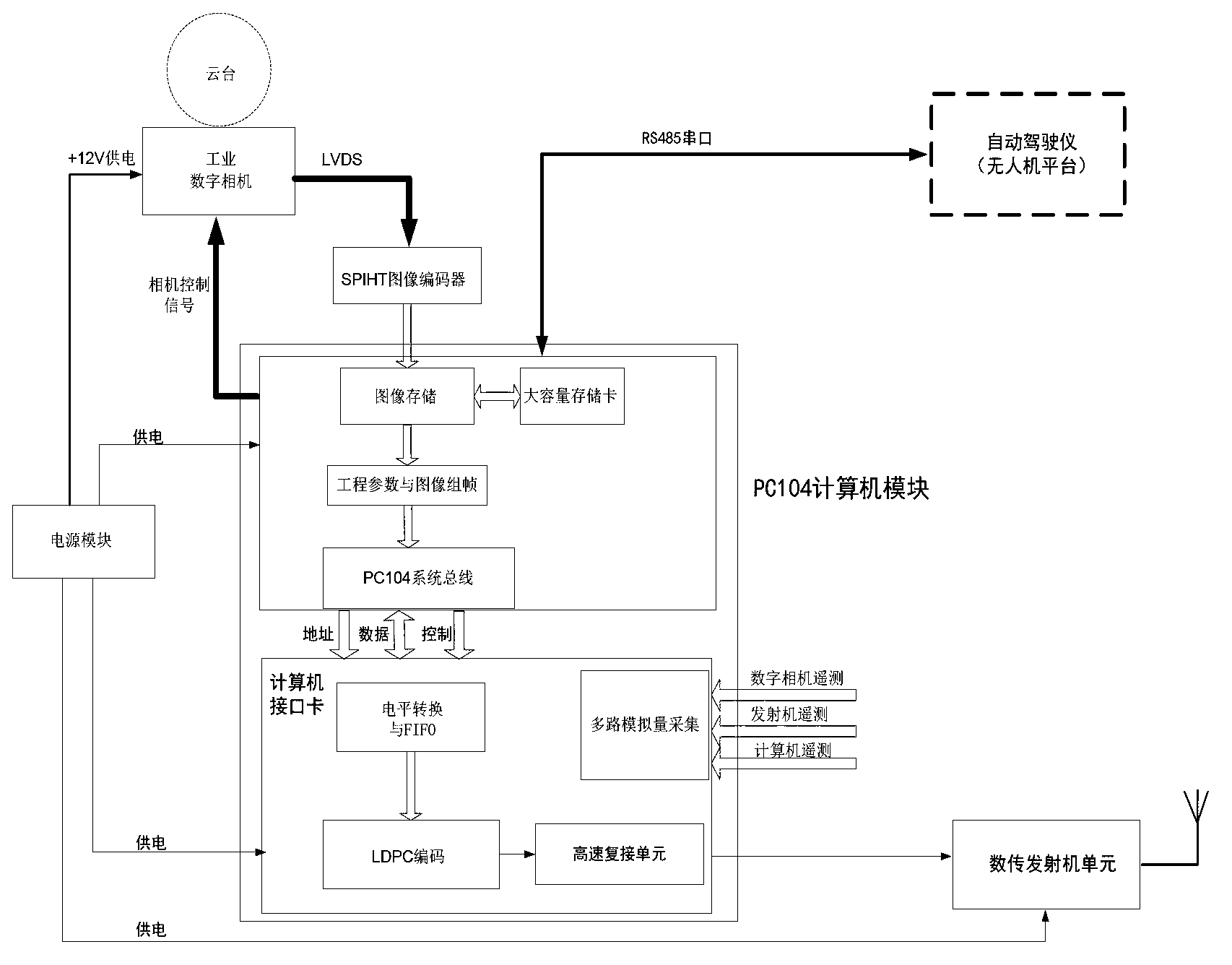
[0054] The UAV image transmission device involved in the present invention specifically refers to the application number "201210167088.7" submitted by the inventor, and the patent application titled "UAV load device with high-resolution real-time wireless image transmission function" An embedded payload device for UAV wireless image transmission, which adds a high-speed image compression hardware module on the basis of traditional wireless image acquisition or image transmission devices, uses microwaves for data transmission, and improves the performance of the digital transmission transmitter. Increase its bandwidth, that is, the main functional modules include: digital camera module, ARM computer module, large-capacity storage module, high-speed FPGA image encoder module, digital transmitter module, regulated power supply module, etc.

[0055...


PUM


Abstract

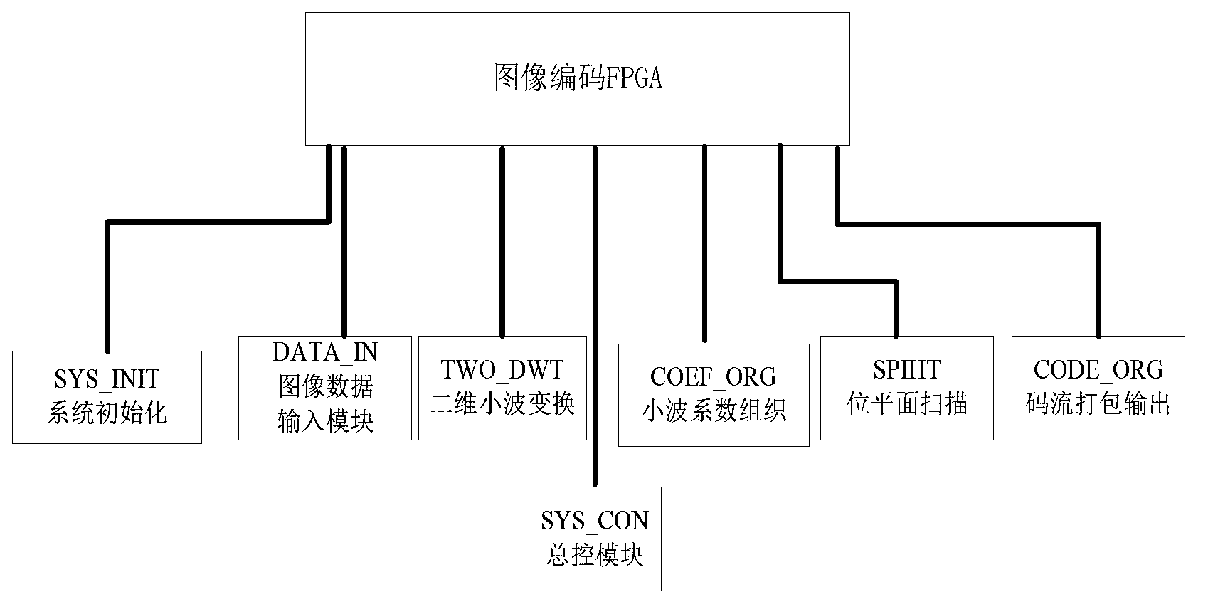
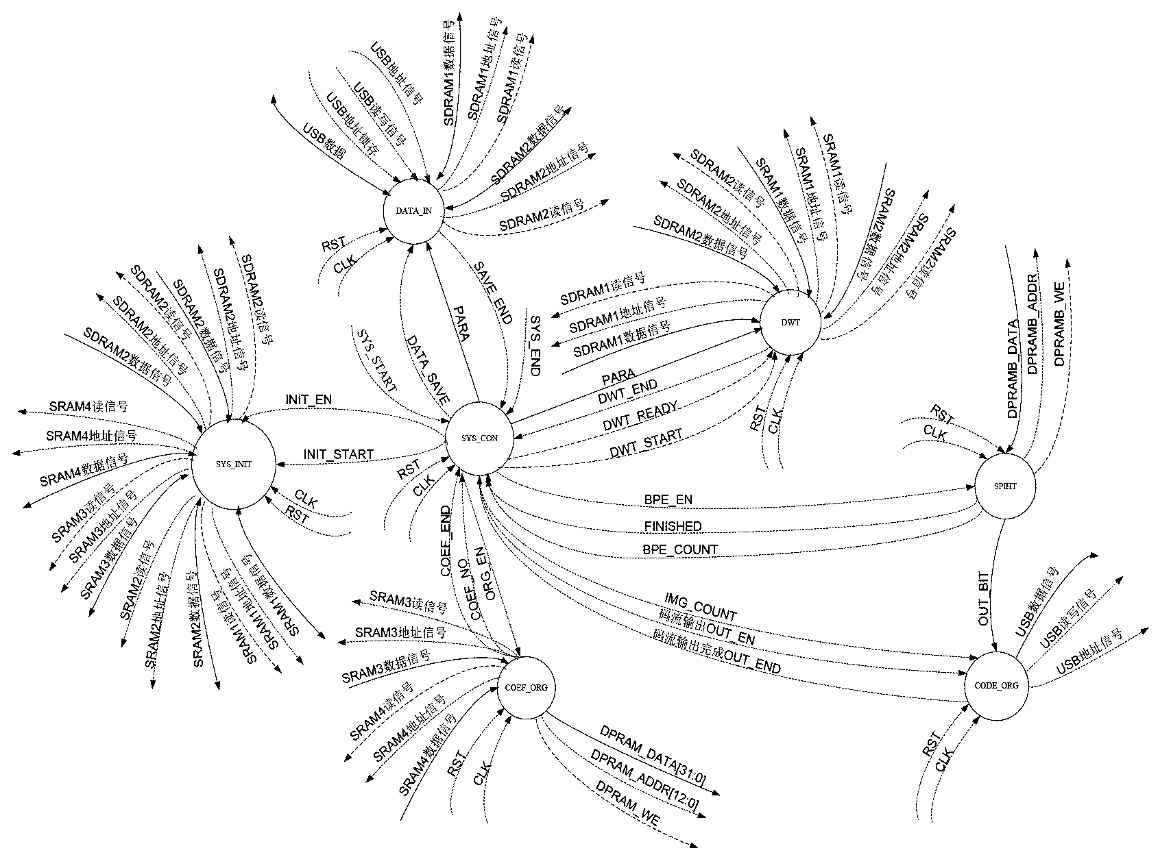
The invention relates to an FPGA encoding method and system and a control method for an unmanned aerial vehicle image transmission device. The system comprises an image input module, a wavelet transformation processing module and an SPIHT algorithm encoding module. The image input module is used for receiving collected image data in real time and conducting conversion in the aspect of a data interface protocol on the collected image data. The wavelet transformation processing module is used for conducting wavelet transformation on image original data after the interface protocol is converted so that wavelet coefficients can be obtained. The SPIHT algorithm encoding module is used for encoding in a bit-plane mode, conducting bit-plane division on the wavelet coefficients to form n bit planes which are scanned in parallel and processing each bit plane to obtain encoded binary code streams. The system further comprises an image encoder general control function module and a system initialization function module, wherein the image encoder general control function module is used for controlling the enable of various function modules in the FPGA encoding system and the enable of a state transition process including an input data processing process, an output data processing process and a middle data processing process, and the system initialization function module is used for initializing the various function modules, memories and registers in the FPGA encoding system and for setting a default state.

Description

technical field [0001] The present invention relates to a high-resolution image encoding method applied to unmanned aerial vehicles, and in particular to a strategy for how to perform high-speed FPGA compression encoding after the unmanned aerial vehicle collects high-resolution images. An FPGA coding system and a control method of a computer image transmission device. Background technique [0002] On the UAV platform, generally speaking, two methods are generally adopted to process the collected high-resolution images. One is directly stored in the airborne large-capacity memory, and transmitted to the ground station in a non-real-time downlink wireless channel. When the drone flies over the area to be measured or reconnaissance, the camera needs to be turned on, and the computer controls the camera to take pictures, and the recorded image data is stored in the solid-state memory. When the drone returns to the ground, the memory card is manually removed. , imported into t...

Claims


Application Information

Patent Timeline
Patent Type & Authority Applications(China)
IPC IPC(8): H04N7/26H04N7/30
Inventor 魏本杰熊蔚明邓永生谢义方
Owner NAT SPACE SCI CENT CAS
Learn More