Photoelectric compound catalysis fluid purification method

A fluid purification, photoelectric composite technology, applied in chemical instruments and methods, separation methods, dispersed particle separation, etc., can solve problems such as low photocatalytic quantum efficiency, achieve improved catalytic conversion efficiency, broad-spectrum oxidation and conversion capacity, increase The effect of contact probability

Inactive Publication Date: 2013-10-02
ZHEJIANG WAKE TECH
View PDF6 Cites 0 Cited by
  • Summary
  • Abstract
  • Description
  • Claims
  • Application Information

AI Technical Summary

Problems solved by technology

Combining the above two causes, in the absence of other auxilia

Method used


Image

  • Photoelectric compound catalysis fluid purification method
  • Photoelectric compound catalysis fluid purification method
  • Photoelectric compound catalysis fluid purification method

Examples


Embodiment 1

[0027] Embodiment one: Purify the mixed gas of 1% formaldehyde and air

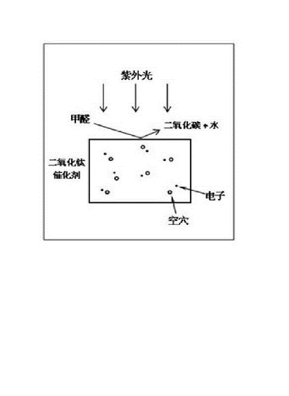
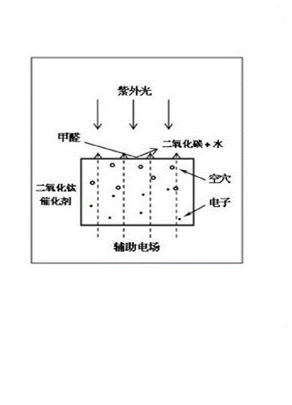
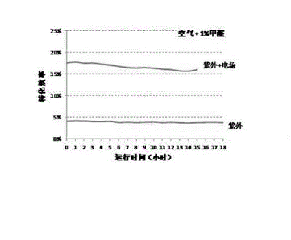
[0028] The simulated pollution gas is a mixture of 1.0%±0.01% formaldehyde and air. The catalyst is titanium dioxide catalyst (TiO 2 ). The ultraviolet light source is an 83W low-pressure mercury lamp. The auxiliary electric field is a static DC voltage of 90 volts. The direction of the electric field is perpendicular to the movement direction of the fluid medium formed by the air in the purification container. The reactant gas composition was analyzed online using a Fuji ZRJ-3 infrared gas analyzer. Test time: 18 hours for conventional photocatalysis; 15 hours for photoelectric composite catalysis. The simulated gas is injected once per hour, and the conversion rate is measured at the same time.

[0029] The experimental results show that after applying the coupled electric field, the oxidation efficiency of formaldehyde is greatly improved, from image 3 As shown, the conversion rate of formaldehy...

Embodiment 2

[0030] Embodiment two: purify the mixed gas of 3% methane and air

[0031] The simulated pollution gas is a mixture of 3.0%±0.01% formaldehyde and air. The catalyst is titanium dioxide catalyst (TiO 2 ). The ultraviolet light source is an 83W high-pressure mercury lamp. The auxiliary electric field is a static DC voltage of 75 volts. The direction of the electric field is perpendicular to the movement direction of the fluid medium formed by the air in the purification container. The reactant gas composition was analyzed online using a Fuji ZRJ-3 infrared gas analyzer. Test time: 14 hours for conventional photocatalysis and photoelectric composite catalysis.

[0032] Experimental results show that after applying a coupled electric field, the oxidation efficiency of methane is also greatly improved, from 10%. like Figure 4 Shown is the change curve of methane conversion rate (ordinate, unit: %) with reaction time (abscissa, unit: hour). It can be seen that the auxiliary...


PUM


Abstract

The invention mainly discloses a photoelectric compound catalysis fluid purification method. The photoelectric compound catalysis fluid purification method comprises the following steps of: adding a catalyst to a purification container, setting ultraviolet ray illumination, and meanwhile, applying an auxiliary electric field in the container; sucking air to be purified from the air inlet of the container, using the auxiliary electric field for realizing the dynamic stripping and surface accumulation of catalyst charges while exciting the ultraviolet ray illumination, and after air is fully in contact with a catalyst, discharging the air from the air outlet of the container. The compound excitation manner of the ultraviolet light plus the auxiliary electric field is adopted in the photoelectric compound catalysis fluid purification method, i.e., the auxiliary orthogonal electric field is applied so as to realize the dynamic stripping and surface accumulation of the charges while a normal light source is excited. The photoelectric compound catalysis fluid purification method can be used for effectively removing a majority of volatile organic gases in air and converting the volatile organic gases into harmless carbon dioxide and water in the end.

Description

technical field [0001] The invention relates to an efficient gas / liquid purification technology at normal temperature, which is suitable for air purification in a non-open environment, especially related to the photoelectric composite catalytic fluid purification method, and is suitable for eliminating organic, harmful and flammable gases or peculiar smells in the air . Background technique [0002] With the massive development of real estate and the continuous improvement of people's housing requirements, more and more man-made materials have entered people's daily life and working environment, such as paints, coatings, furniture and decoration materials made of composite materials, plastics All kinds of electrical enclosures and so on. Most of these man-made materials have undergone chemical treatment, or some chemical agents, such as solvents, have been used in the preparation process. These chemical agents are more or less harmful to human health. Although manufacture...

Claims


Application Information

Patent Timeline
IPC IPC(8): B01D53/76B01D53/86B01D53/44
Inventor 夏越明夏琦毛茜倩
Owner ZHEJIANG WAKE TECH
Why Eureka
Try Eureka