Magnetic bevel gear for non-contact type space crossing driving and manufacturing method and application thereof

A cross-drive, non-contact technology, applied in the direction of transmission, belt/chain/gear, components with teeth, etc., can solve the problems of inability to realize large torque transmission, small rotation radius of transmission magnetic gear, etc., and achieve simple structure , Small vibration, easy to make effect

Inactive Publication Date: 2013-10-02
SHANGHAI UNIV
View PDF7 Cites 2 Cited by
  • Summary
  • Abstract
  • Description
  • Claims
  • Application Information

AI Technical Summary

Problems solved by technology

The transmission magnetic gears between the non-contact space cross shafts that have been proposed have a small turning radius and cannot realize large torque transmission

Method used


Image

  • Magnetic bevel gear for non-contact type space crossing driving and manufacturing method and application thereof
  • Magnetic bevel gear for non-contact type space crossing driving and manufacturing method and application thereof

Examples


Embodiment 1

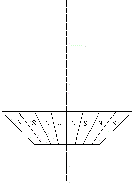
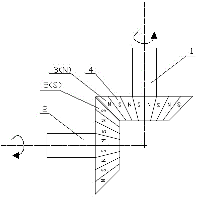
[0018] See figure 1 , The magnetic bevel gear for non-contact spatial cross transmission includes a magnetic bevel gear, which is characterized by:

[0019] 1) Its magnetic poles are evenly distributed on the tapered surface of the magnetic bevel gear with the S pole and the N pole interval,

[0020] 2) The magnetic poles are arranged circumferentially in a trapezoidal shape,

[0021] 3) The arrangement of all magnetic poles forms a smooth and complete cone.

Embodiment 2

[0023] This embodiment is basically the same as the first embodiment. The special feature is that the entire tapered shaft end is a bonded compact of neodymium iron boron, and its magnetic pole is formed by a radial multi-pole magnetizing structure on the external surface of the bonded compact magnetic pole.

Embodiment 3

[0025] The method for manufacturing magnetic bevel gears for non-contact spatial cross transmission is used for manufacturing according to the claims

[0026] The magnetic bevel gear for non-contact spatial cross transmission is characterized in that the tapered shaft end of the magnetic bevel gear is made of neodymium iron boron permanent magnet material through bonding and pressing, and then the tapered surface is obtained by radial multi-pole magnetization magnetic pole.


PUM


Abstract

The invention relates to a magnetic bevel gear for non-contact type space crossing driving and a manufacturing method and an application thereof. The magnetic bevel gear is applied to a dustless production delivering mechanism and equipment with a driving demand on a space crossing shaft. The magnetic bevel gear comprises a ferric shaft and a tapered shaft end formed by splicing and pressing a neodymium iron boron permanent magnetic material, wherein magnetic poles are mostly obtained by magnetizing along a radial direction through multi-pole and are uniformly distributed in a ladder shape on a tapered plane of the tapered shaft end, and the adjacent magnetic poles are hetero-poles. Two magnetic gears are mounted and used in a space crossing form, the two magnetic bevel gears are in a non-contact mode, an effective clearance is remained between the two magnetic bevel gears, and a torque can be generated by an attractive force and a repulsive force between the magnetic poles, so that a driven gear is driven to rotate by a driving gear. The magnetic bevel gear has the advantages of simple structure, convenience in maintenance, high carrying capacity, dust prevention, mechanical wearing prevention, low noise, small vibration, safety, reliability, long service life, and the like.

Description

Technical field [0001] The invention relates to a magnetic bevel gear and a manufacturing method and application thereof, in particular to a magnetic bevel gear for non-contact spatial cross transmission, and a manufacturing method and application thereof. The bevel gear is used in transmission devices or equipment, and is especially used in the occasions where dust-free production environment is required, and the transmission direction of the shaft has a large torque transmission device or equipment that requires a space to cross. Background technique [0002] The traditional mechanical gear transmission mechanism, because it is all contact transmission, inevitably generates particles and dust during the workpiece process. In some high-tech fields, the requirements for the production environment are very strict, so in today's transmission technology, non-gear contact magnetic gears with high cleanliness and no wear have emerged. However, in the previous technology of ma...

Claims


Application Information

Patent Timeline
IPC IPC(8): F16H55/17F16H55/06F16H49/00
Inventor 孙涛张洪督
Owner SHANGHAI UNIV
Why Eureka
Try Eureka