Micro-tension sensor for automatic winding machine
An automatic winding machine and micro-tension technology, which is applied in the direction of conveying filamentous materials, thin material processing, transportation and packaging, etc., can solve the problems of difficult detection accuracy, inconvenient installation, complex overall structure, etc., and achieve good detection accuracy , Contribute to the production and reflect the effect of economy
- Summary
- Abstract
- Description
- Claims
- Application Information
AI Technical Summary
Problems solved by technology
Method used
Image
Examples
Embodiment 1
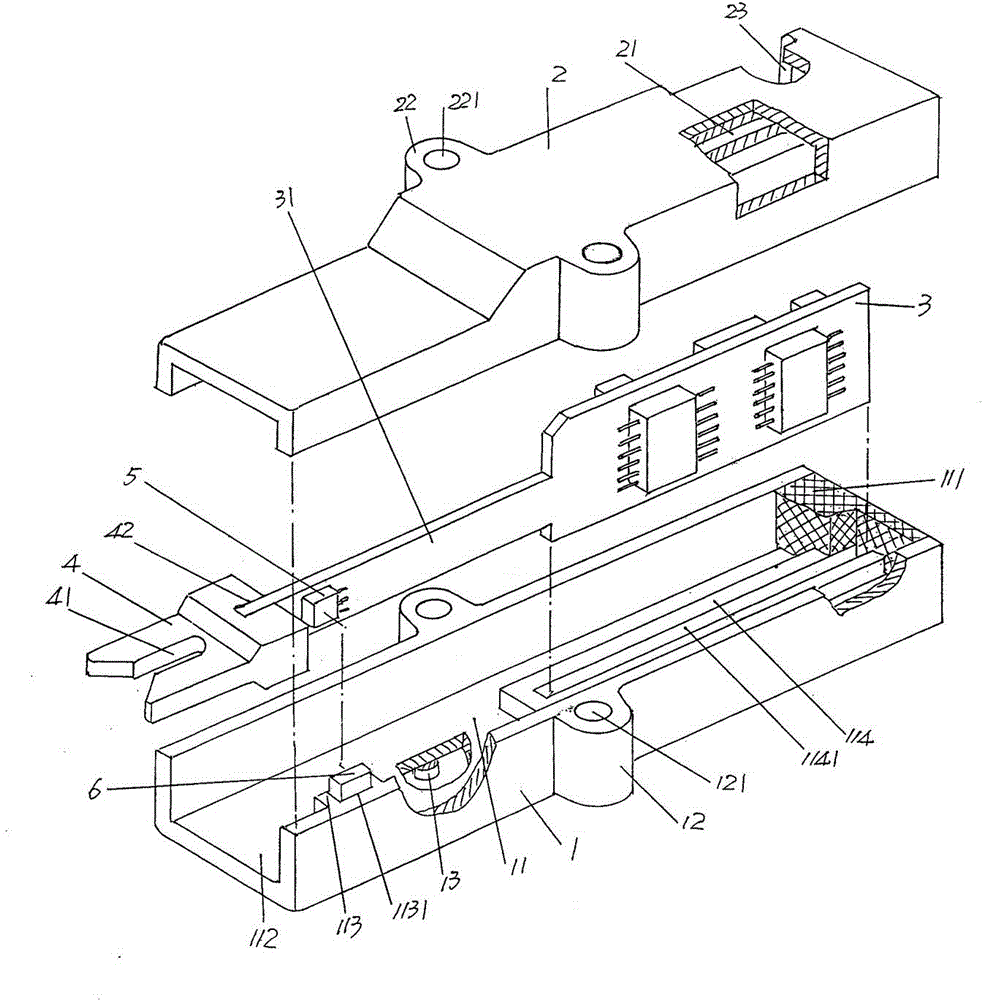
[0026] See figure 1 , a housing 1 is provided, the housing 1 is formed with a shell cavity 11, and one end of the shell cavity 11 forms a cavity opening 112, and a control circuit board is formed in the shell cavity 11 and at the other end of the shell cavity 11 The fixing seat 114 forms a control circuit board insertion groove 1141 on the side facing upwards in the length direction of the control circuit board 114, and the entire shell cavity 11 is filled with damping glue 111, which is silicone gel ( Silicone gel), this kind of damping glue is like the jelly that belongs to the food category seen in daily life, with good elasticity and elastic recovery ability. In this embodiment, the silicone gel is preferably RB-AY silicone gel produced by Xingshan Plastic Products Co., Ltd., Shantou City, Guangdong Province, China and sold in the market before the filing of this patent application. On both sides of the length direction of the housing 1 and generally located in the middle...
Embodiment 2
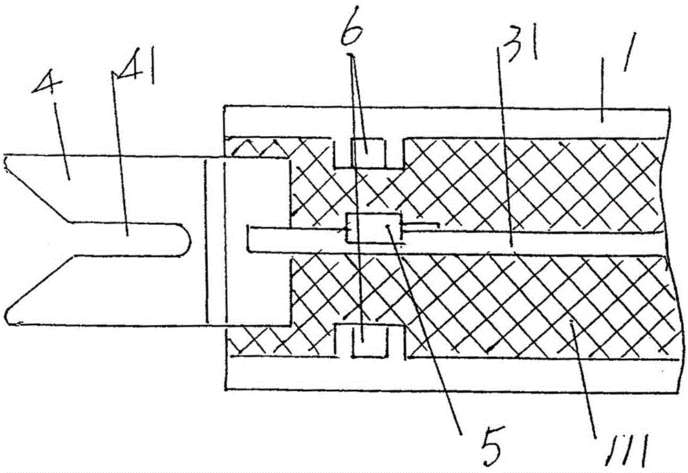
[0035] See figure 2 and combine figure 1 At the aforementioned one end of the shell cavity 11 and on the cavity wall located on one side and the other side of the one end, there are respectively formed a magnet component fixing seats 113 corresponding to positions bulging (protruding) toward the shell cavity 11, and also That is to say, the magnet component fixing base 113 has a pair facing each other, and each magnet component fixing base 113 is provided with a magnet component embedding cavity 1131, and the bottom of the magnet component 6 is embedded in each magnet component embedding cavity 1131, and the magnet The upper part of the component 6 protrudes out of the magnet component insertion cavity 1131, and the aforementioned signal collector 5 is fixed on the lower or upper part of the guide sheet fixing rod 31 (that is, to meet the requirement that the signal collector 5 protrudes out of the yarn guide sheet fixing rod 31), so as to correspond to a pair of magnet part...
Embodiment 3
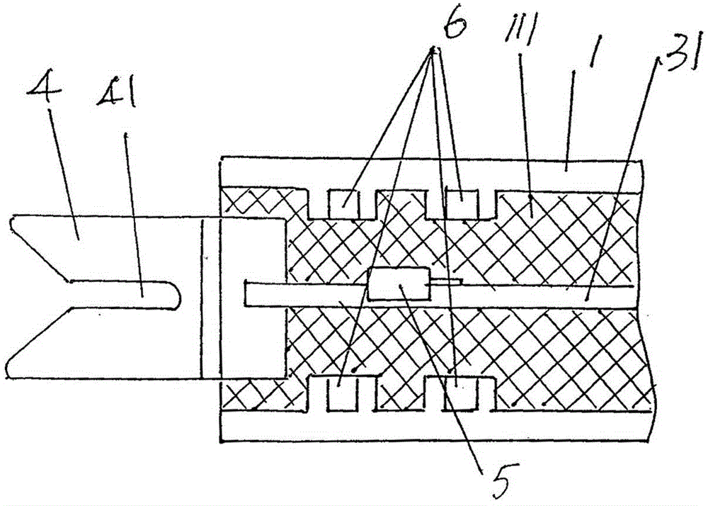
[0037] See image 3 and combine figure 1 , a pair (two) of magnet components corresponding to each other are formed on the wall of the aforementioned one end of the shell cavity 11 and on one side of the end and the other side The fixed base 113 has a magnet component embedding cavity 1131 on each magnet component fixing base 113, and the bottom of the magnet component 6 is embedded in each magnet component embedding cavity 1131, and the top of the magnet component 6 protrudes out of the magnet component embedding cavity. Set cavity 1131. The aforementioned signal collector 5 is fixed on the lower or upper part of the guide sheet fixing rod 31 (that is, to meet the requirement that the signal collector 5 protrudes out of the guide sheet fixing rod 31), so as to correspond to the four magnet parts 6, that is, the signal The collector 5 is located at the intersection of the diagonals of the four magnet parts 6, because the four magnet parts 6 are distributed in the shape of a ...
PUM
 Abstract
Description
Claims
Application Information
 - R&D
- Intellectual Property
- Life Sciences
- Materials
- Tech Scout
- Unparalleled Data Quality
- Higher Quality Content
- 60% Fewer Hallucinations
Browse by: Latest US Patents, China's latest patents, Technical Efficacy Thesaurus, Application Domain, Technology Topic, Popular Technical Reports.
© 2025 PatSnap. All rights reserved.Legal|Privacy policy|Modern Slavery Act Transparency Statement|Sitemap|About US| Contact US: help@patsnap.com


