Device and method for measuring non-isoplanatism wave-front errors and turbulence characteristic parameters of atmosphere turbulence

A technique for atmospheric turbulence and wavefront error, applied in the field of optical information measurement, can solve the problems of high engineering requirements and inability to obtain two-dimensional distribution information of turbulent non-isohalo wavefront error

Active Publication Date: 2013-10-02
INST OF OPTICS & ELECTRONICS - CHINESE ACAD OF SCI
View PDF6 Cites 16 Cited by
  • Summary
  • Abstract
  • Description
  • Claims
  • Application Information

AI Technical Summary

Problems solved by technology

However, when measuring the coherence length of this method, it is necessary to use two telescope systems that are exactly the same and have specific requirements for the distance between the centers of the optical paths to receive differential star images; when measuring the equi-halo angle, it is required to control the receiving aperture of the system to meet the requirements of

Method used


Image

  • Device and method for measuring non-isoplanatism wave-front errors and turbulence characteristic parameters of atmosphere turbulence
  • Device and method for measuring non-isoplanatism wave-front errors and turbulence characteristic parameters of atmosphere turbulence
  • Device and method for measuring non-isoplanatism wave-front errors and turbulence characteristic parameters of atmosphere turbulence

Examples


Embodiment 1

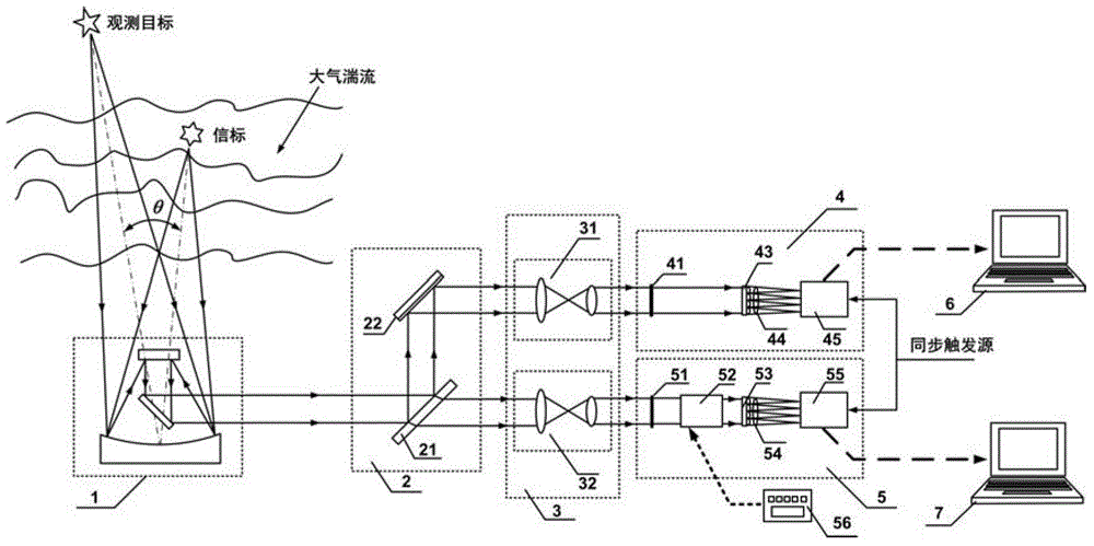
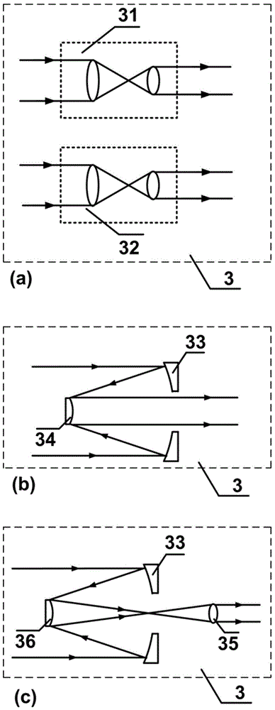
[0044] The atmospheric turbulent non-isohalotic wavefront error and turbulent characteristic parameter measuring device of the present invention mainly includes a telescope 1, a light splitting module 2, a beam shrinking module 3, a target Hartmann sensor 4 and a corresponding wavefront processor 6, Beacon Hartmann sensor 5 and its corresponding wavefront processor 7 . Wherein, the spectroscopic module 2 is composed of a spectroscopic mirror 21 and a reflecting mirror 22, which can exchange positions with each other. The attenuator module 3 can be used as figure 2 The transmissive structure shown in (a) can also be used as figure 2 (b) and (c) respectively show the reflection structure, reflection and transmission combined structure. The beam splitting module 2 and the beam shrinking module 3 can also exchange positions with each other, that is, the method of first splitting the beam and then shrinking the beam, or the method of first reducing the beam and then splitting t...

Embodiment 2

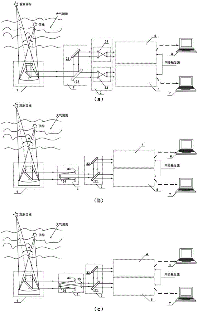
[0087] Such as Figure 6 Shown is a specific implementation of the measurement device and method of the atmospheric turbulence anisotropic wavefront error and turbulence characteristic parameters of the present invention to realize the angular anisotropic wavefront error measurement in the natural beacon mode.

[0088]The device consists of a telescope 1, a spectroscopic module 2, a beam reduction module 3, a target Hartmann sensor 4 and its corresponding wavefront processor 6, a beacon Hartmann sensor 5 and its corresponding wavefront processor 7, etc. composition. In this embodiment, the beam splitting module 2 is composed of a beam splitter 21 and a reflector 22 ; the beam shrinking module 3 is composed of two identical transmission beam shrinking mirror groups 31 and 32 . The target Hartmann sensor 4 is mainly composed of a microlens group 43, a matching lens 44 and a CCD camera 45, and a filter 41 is placed in the center of the optical path perpendicular to its optical a...

Embodiment 3

[0098] Such as Figure 7 Shown is a specific implementation of the measurement device and method of atmospheric turbulence anisotropic wavefront error and turbulence characteristic parameters of the present invention to realize the measurement of angle and focus comprehensive anisotropic wavefront error in artificial beacon mode.

[0099] The external structure of the artificial beacon angle and focus integrated anisotropic wavefront error device provided in this embodiment is the same as that in Embodiment 2. Due to the characteristic wavelength of the artificial beacon, the difference between this embodiment and embodiment 2 is that the filter 41 in the target Hartmann sensor 4 and the filter 51 in the beacon Hartmann sensor 5 in embodiment 1 are respectively Replaced with a notch filter 47 and a narrowband filter 57 (corresponding to the artificial beacon wavelength λ).

[0100] The working principle of this embodiment is briefly described as follows:

[0101] (1) Under t...


PUM


Abstract

The invention provides a device and a method for measuring non-isoplanatism wave-front errors and turbulence characteristic parameters of an atmosphere turbulence. The method comprises the following steps: setting a beacon Hartmann sensor focusing distance according to a beacon mode; respectively receiving a target light wave imaging light spot pattern and a beacon light wave imaging light spot pattern by utilizing a target Hartmann sensor and a beacon Hartmann sensor; controlling a target Hartmann sensor CCD (Charge Coupled Device) and a beacon Hartmann sensor CCD to synchronously collect by an external synchronous triggering source; calculating an average slope of a time sequence target light wave and a beacon light wave in a sub-hole diameter of a micro-lens set, and carrying out difference operation by utilizing a wave-front processor; carrying out recovery on a difference average slope and a target light wave average slope and expanding a Zernike mode by utilizing a recovering algorithm to obtain counting characteristics including non-isoplanatism wave-front errors, target turbulence wave-front two-dimensional distribution, wave-front square errors, a P-V value, Zernike mode square errors, non-isoplanatism relative errors and the like, as well as the turbulence characteristic parameters including the coherence length, an isoplanatic angle, the beacon equivalent diameter and the like. The device and method disclosed by the invention have the advantages of high light energy utilization rate, small measurement errors and wide application prospect.

Description

technical field [0001] The invention belongs to the technical field of optical information measurement, and relates to a device and method for measuring atmospheric turbulent anisotropic wavefront errors and turbulent characteristic parameters, specifically measuring the atmospheric turbulent anisotropic wavefront errors and turbulence characteristic parameters based on a Hartmann sensor. A device and method for measuring turbulence characteristic parameters. Background technique [0002] The atmosphere is the basic channel for light wave transmission in many practical optical applications such as astronomical observation and laser atmospheric transmission. Due to the random fluctuation of atmospheric refractive index due to turbulent motion caused by factors such as human activities and solar radiation, the target light wave suffers severe wavefront distortion, which has become an important factor limiting the performance of practical optical systems. [0003] Adaptive Opt...

Claims


Application Information

Patent Timeline
IPC IPC(8): G01N21/17
Inventor 李新阳罗曦邵力黄奎胡诗杰田雨李敏
Owner INST OF OPTICS & ELECTRONICS - CHINESE ACAD OF SCI
Why Eureka
Try Eureka