
Three-freedom-degree constant speed decoupling space robot active spherical wrist and universal compliant control method

A space robot and constant velocity gimbal technology, applied in manipulators, manufacturing tools, joints, etc., can solve the problems of spherical wrist gimbal compliant control mode of space robots without three degrees of freedom constant velocity decoupling, and achieve uniform speed control Simple and easy to implement, realize the effect of motion decoupling, and realize the effect of constant velocity and large angle rotation

Active Publication Date: 2013-10-09
DALIAN UNIV OF TECH
View PDF4 Cites 59 Cited by
  • Summary
  • Abstract
  • Description
  • Claims
  • Application Information

AI Technical Summary

Problems solved by technology

[0022] According to the information we have and the novelty search of the project, there is no report on the research on the universal compliant control mode of the three-degree-of-freedom constant-velocity decoupling space robot at home and abroad. Therefore, this patent has a relatively prominent originality

Method used


Image

  • Three-freedom-degree constant speed decoupling space robot active spherical wrist and universal compliant control method
  • Three-freedom-degree constant speed decoupling space robot active spherical wrist and universal compliant control method
  • Three-freedom-degree constant speed decoupling space robot active spherical wrist and universal compliant control method

Examples


Embodiment Construction

[0056] Specific embodiments of the present invention will be described in detail below in conjunction with technical solutions and accompanying drawings.

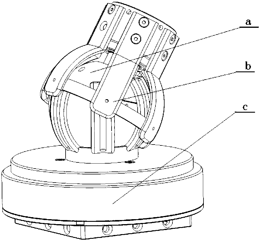
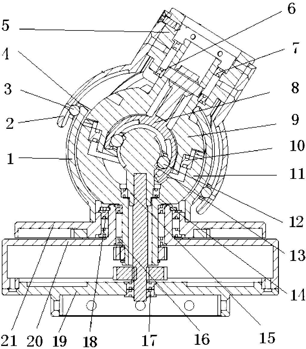
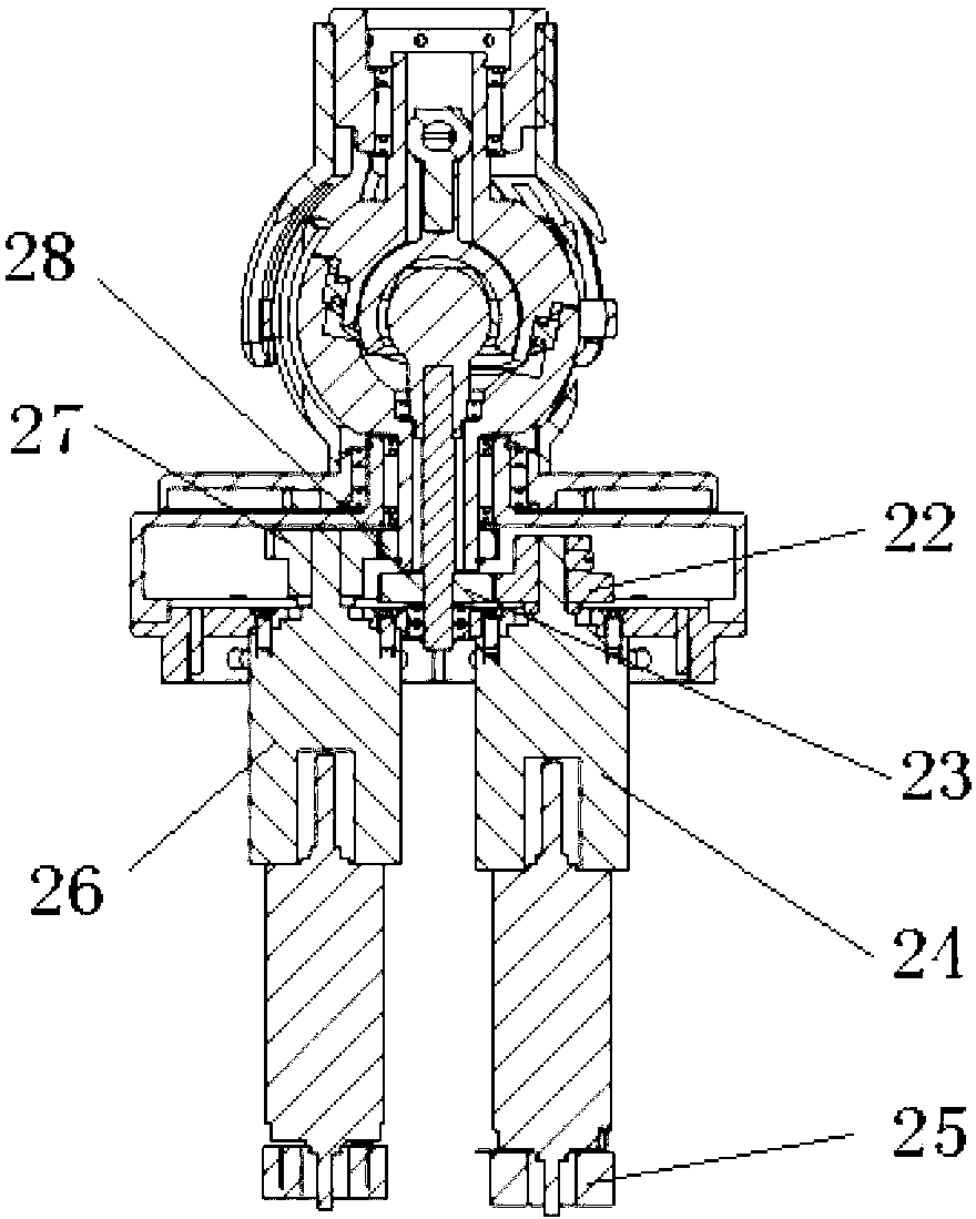
[0057] combined with figure 2 , Figure 3(A) and 3(C) Explain the realization of the three-degree-of-freedom constant-velocity decoupling spherical wrist side swing and pitch motion. The active wrist of the three-degree-of-freedom constant-velocity decoupling spherical robot includes an internal spherical cage constant velocity universal joint, which includes a spherical shell 8, six Steel ball 12, steel ball cage 13 and star-shaped sleeve 15, the power is transmitted from star-shaped sleeve 15 to spherical shell 8 through steel ball 12 for output, spherical shell 8 and star-shaped sleeve 15 have the same spherical center, that is, the inner spherical cage is constant velocity The center of rotation of the gimbal.

[0058]The side swing and pitch motion mechanism of the active wrist of the three-degree-of-freedom consta...


PUM


Abstract

The invention relates to a three-freedom-degree constant speed decoupling space robot active spherical wrist and a universal compliant control method. The offset mode that the included angles are formed among rotation plane normal and rotating shafts is adopted for both an upper hemisphere rotating body and a lower hemisphere rotating body. The intersection point of the two rotating shafts of the upper rotating body and the lower rotating body is the sphere center of hemispheres of the upper rotating body and the lower rotating body, the intersection point of the two rotating shafts coincides with the rotating center of an inner ball cage universal joint and the rotating center of an outer ball cage universal joint respectively, and then constant speed decoupling of three input movements is achieved; the output end of the outer ball cage universal joint is connected with a shaft neck of the upper rotating body through a bearing in a suspension mode, three absolute corner coded discs are connected with the upper rotating body, the lower rotating body, a motor conducting spinning motion, and the output end of a speed reducing system respectively, a six-dimensional ATI sensor is installed at the output tail end of the wrist, and a wrist universal compliant follow-up control mode is achieved by a rotating joint of an upper hemisphere, a rotating joint of a lower hemisphere and a joint conducting spinning motion through a system friction force compensation technology. The three-freedom-degree constant speed decoupling space robot active spherical wrist and the universal compliant control method are accurate in locating, stable in movement, and capable of avoiding oscillation phenomena of movement coupling and mechanical arms and effectively relieving mechanical interference in a spherical wrist full compliant mode.

Description

technical field [0001] The invention belongs to the technical field of automation engineering, and relates to a three-degree-of-freedom constant speed that drives upper and lower offset rotating bodies to synthesize side swing, pitch, and output end suspension rotation motion through an inner and outer spherical cage type universal joint transmission mechanism Decoupling the highly integrated active spherical wrist mechanism of space robots and a system friction feed-forward compensation method through the three rotating joints of the wrist to realize the interactive force of the spherical wrist following the end under the conditions of aerospace contact operations to eliminate force interference Universal compliance control method. Background technique [0002] Space robots play an important role in the maintenance and daily work of space laboratories or space stations, such as the assembly of space cabins, maintenance of spacecraft, control of spacecraft and opening of hat...

Claims


Application Information

Patent Timeline
IPC IPC(8): B25J17/00B25J13/00
Inventor 张永顺郑鹏王殿龙满达
Owner DALIAN UNIV OF TECH
Learn More