Method for degrading organic pollutants in water through electrochemical cathodic activation of persulfate
A technology of organic pollutants and persulfate, applied in the direction of electrochemical water/sewage treatment, water pollutants, chemical instruments and methods, etc., can solve problems such as residual ferric ions, iron sludge, and complicated operations. Achieve the effects of simple operation, avoiding secondary pollution and low energy consumption
- Summary
- Abstract
- Description
- Claims
- Application Information
AI Technical Summary
Problems solved by technology
Method used
Image
Examples
specific Embodiment approach 1
[0016] Specific embodiment one: present embodiment is a kind of method of electrochemical cathodic activation of persulfate degrading organic pollutants in water, specifically completes according to the following steps:
[0017] The water polluted by organic matter to be treated is injected into the cathode / anode electrode pair reactor, and then persulfate is added until the concentration of persulfate is 0.01mmol / L-100mmol / L, and then the concentration of persulfate is 0.01mmol / L~100mmol / L and the cathode electrode voltage is +2.0V~-2.5V, and the treatment is 2min~180min, and the water treatment of the organic matter pollution to be treated is completed.
specific Embodiment approach 2
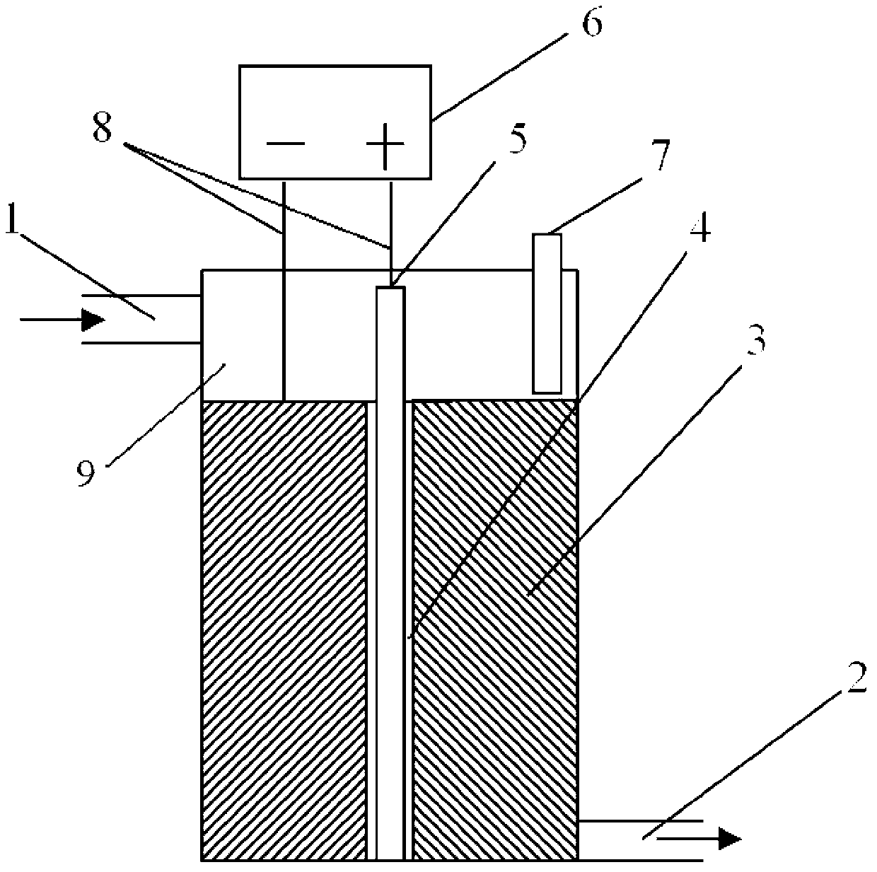
[0018] Specific implementation mode two: combination figure 1 The difference between this embodiment and specific embodiment 1 is: the cathode / anode electrode pair reactor includes a water inlet 1, a water outlet 2, a cathode 3, an insulating porous isolation tube 4, an anode 5, a DC power supply 6, a reference Compared with the electrode 7, the wire 8 and the reaction chamber 9, the water inlet 1 is arranged on the upper side wall of the reaction chamber 9, and the water outlet 2 is arranged on the lower side wall of the symmetrical side of the reaction chamber 9, and the anode 5 is arranged in the reaction chamber 9 In the center, the cathode 3 wraps the anode 5 and covers the space of the reaction chamber 9 below the water inlet 1, the cathode 3 and the anode 5 are separated by the insulating porous isolation tube 4, and the cathode 3 and the anode 5 are respectively connected to the DC power supply 6 by the wire 8 The negative pole and the positive pole are connected corre...
specific Embodiment approach 3
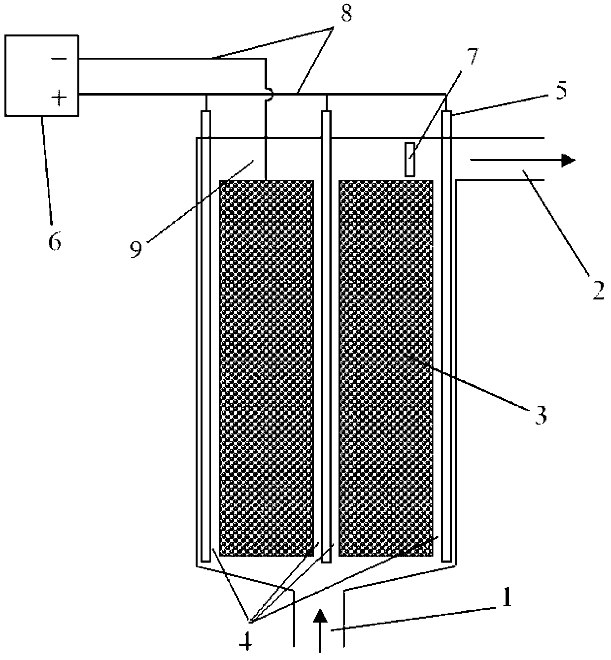
[0021] Specific implementation mode three: combination figure 2 The difference between this embodiment and specific embodiment 1 is: the cathode / anode electrode pair reactor includes a water inlet 1, a water outlet 2, a cathode 3, an insulating porous isolation tube 4, a number of anodes 5, a DC power supply 6, Reference electrode 7, wire 8 and reaction chamber 9, water inlet 1 is set at the bottom of reaction chamber 9, water outlet 2 is set on the upper side wall of reaction chamber 9, cathode 3 is covered with water outlet 2 below the form of fluidized bed In the space of the reaction chamber 9, some anodes 5 are interspersed in the cathode 3, and the cathode 3 is separated from some anodes 5 by an insulating porous isolation tube 4, and some anodes 5 are connected in parallel by a wire 8, and then connected to the positive pole of the DC power supply 6, The cathode is connected to the negative pole of the DC power supply 6 by a wire 8 , and the reference electrode 7 is su...
PUM
 Abstract
Description
Claims
Application Information
 - R&D
- Intellectual Property
- Life Sciences
- Materials
- Tech Scout
- Unparalleled Data Quality
- Higher Quality Content
- 60% Fewer Hallucinations
Browse by: Latest US Patents, China's latest patents, Technical Efficacy Thesaurus, Application Domain, Technology Topic, Popular Technical Reports.
© 2025 PatSnap. All rights reserved.Legal|Privacy policy|Modern Slavery Act Transparency Statement|Sitemap|About US| Contact US: help@patsnap.com


