Single-hole single-pushing glost firing kiln utilizing residual heat of cooling area of high-temperature electrical kiln

A cooling zone, single hole single technology, applied in the kiln field, can solve the problems of large loss of sagger, large investment, high energy consumption, etc., and achieve the effect of convenient operation, reduced energy waste, and reduced energy consumption

Inactive Publication Date: 2013-10-09
陈秋生
View PDF5 Cites 4 Cited by
  • Summary
  • Abstract
  • Description
  • Claims
  • Application Information

AI Technical Summary

Problems solved by technology

[0003] The invention provides a single-hole single-push glaze kiln utilizing the residual temperature in the cooling zone of the high-temperature push-plate electric kiln, and aims to solve the problem of large investment in existing single-hole single-push kiln equipment, large loss of saggers, and The problem of high energy consumption

Method used


Image

  • Single-hole single-pushing glost firing kiln utilizing residual heat of cooling area of high-temperature electrical kiln
  • Single-hole single-pushing glost firing kiln utilizing residual heat of cooling area of high-temperature electrical kiln

Examples


Embodiment Construction

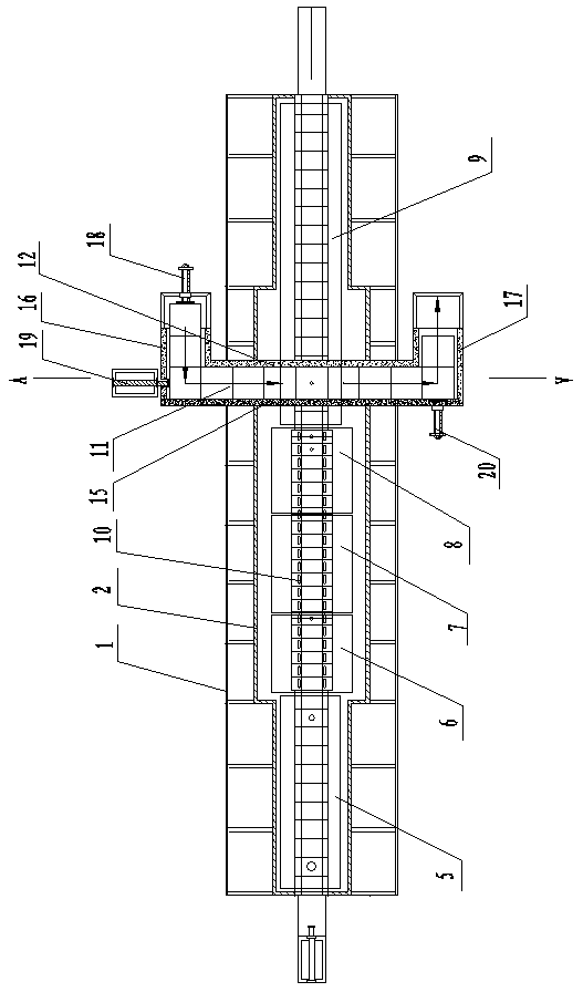
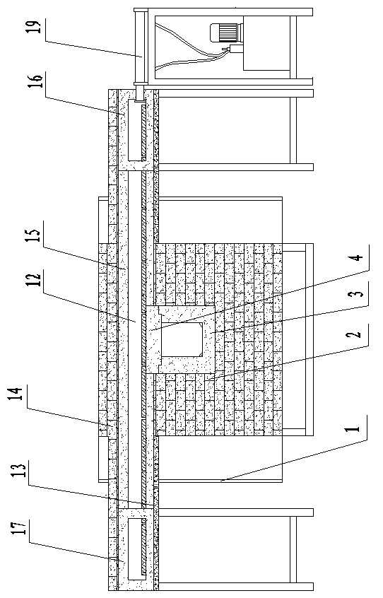
[0011] Such as figure 1 As shown, the kiln includes 1700℃ high temperature pusher electric kiln shell 1, 1700℃ high temperature pusher electric kiln body 2, 1700℃ high temperature pusher electric kiln body 2 is set at 1700℃ high temperature pusher electric kiln shell 1. Inside, 1700℃ high temperature push plate electric kiln body 2. Inside the kiln body 2 is equipped with inner liner 3, top brick 4, the top brick 4 is matched with the upper top of the inner liner 3, the inner liner 3, top brick 4 push the plate electric kiln from 1700℃ high temperature The inlet end of the kiln body 2 to the outlet end of the 1700℃ high-temperature push-plate electric kiln body 2 is filled in rows one by one. The 1700℃ high-temperature push-plate electric kiln body 2 is located in preheating zone 5 and low temperature zone from front to back. 6. The high temperature zone 7, the constant temperature zone 8, the cooling zone 9, the low temperature zone 6, the high temperature zone 7, and the const...


PUM


Abstract

The invention discloses a single-hole single-pushing glost firing kiln utilizing residual heat of a cooling area of a high-temperature electrical kiln, and relates to a kiln. The single-hole single-pushing glost firing kiln comprises a shell body of a high-temperature push plate electrical kiln with 1700 DEG C and a kiln body of the high-temperature push plate electrical kiln with 1700 DEG C, an inner container and a crown brick are arranged in the kiln body of the high-temperature push plate electrical kiln with 1700 DEG C, the crown brick is matched at the upper top end of the inner container, a pre-heating area, a low temperature area, a high temperature area, a constant temperature area and the cooling area are respectively arranged inside the kiln body of the high-temperature push plate electrical kiln with 1700 DEG C from front to back in sequence, a plurality of silicon molybdenum rods are arranged in the low temperature area, the high temperature area and the constant temperature area, and a single-hole single-pushing glost firing kiln body is arranged above the cooling area of the kiln body of the high-temperature push plate electrical kiln with 1700 DEG C and is communicated with the cooling area of the kiln body of the high-temperature push plate electrical kiln with 1700 DEG C. The kiln can utilize waste heat to carrying out firing, reduces energy consumption, and meanwhile reduces energy waste, a kiln body does not need to be additionally built for the glost firing kiln, and equipment funds are reduced.

Description

Technical field [0001] The invention relates to a kiln, in particular to an energy-saving kiln which utilizes the waste heat of the cooling zone of a single-hole single-push high-temperature pusher electric kiln during glazing and sintering on the surface of ceramic parts. Background technique [0002] The surface of alumina ceramic parts, especially the burner ignition needle and induction needle ceramic parts, must be coated with a glaze layer to ensure infinite surface resistance under the condition of high air humidity; if the glaze layer is not coated, the surface will be caused by moisture absorption Short circuit affects the insulation effect; due to the high firing temperature of alumina ceramic parts (around 1700°C), a single-hole single-push or double-hole counter-push high-temperature electric kiln with silicon molybdenum rods as heating elements is generally used; The firing temperature of the firing glaze layer (abbreviated as: firing glaze) is about 1200℃. Generally...

Claims


Application Information

Patent Timeline
Patent Type & Authority Applications(China)
IPC IPC(8): F27B9/02F27B9/30F27D17/00
Inventor 陈秋生
Owner 陈秋生
Why Eureka
Try Eureka