
Method for constructing light gauge welding residual stress field on basis of small-hole process tested data

A technology of residual stress and test data, which is applied in the field of thin plate welding residual stress field based on small hole method test data, can solve the problems of large amount of calculation in the process of structural stress, low accuracy of test data, and large amount of test data, etc., to reduce calculation Quantity, convenient operation, and the effect of improving efficiency

Inactive Publication Date: 2013-10-09
JIANGSU UNIV OF SCI & TECH
View PDF2 Cites 13 Cited by
  • Summary
  • Abstract
  • Description
  • Claims
  • Application Information

AI Technical Summary

Problems solved by technology

For the choice of function to characterize the eigenstrain, Korsunsky et al. used two directional coordinates as polynomials of variables, which would cause a large amount of calculation in the entire tectonic stress process
[0006] The existing residual stress test can only reflect the local stress results, and the numerical calculation cannot be calculated in the case of insufficient calculation parameters; at the same time, the existing method of using a small amount of test data to obtain the intrinsic strain distribution to construct the welding residual stress field also exists Low accuracy of test data, large amount of test data, and large amount of calculation

Method used


Image

  • Method for constructing light gauge welding residual stress field on basis of small-hole process tested data
  • Method for constructing light gauge welding residual stress field on basis of small-hole process tested data
  • Method for constructing light gauge welding residual stress field on basis of small-hole process tested data

Examples


Embodiment Construction

[0031] The present invention will be further explained below in conjunction with the drawings.

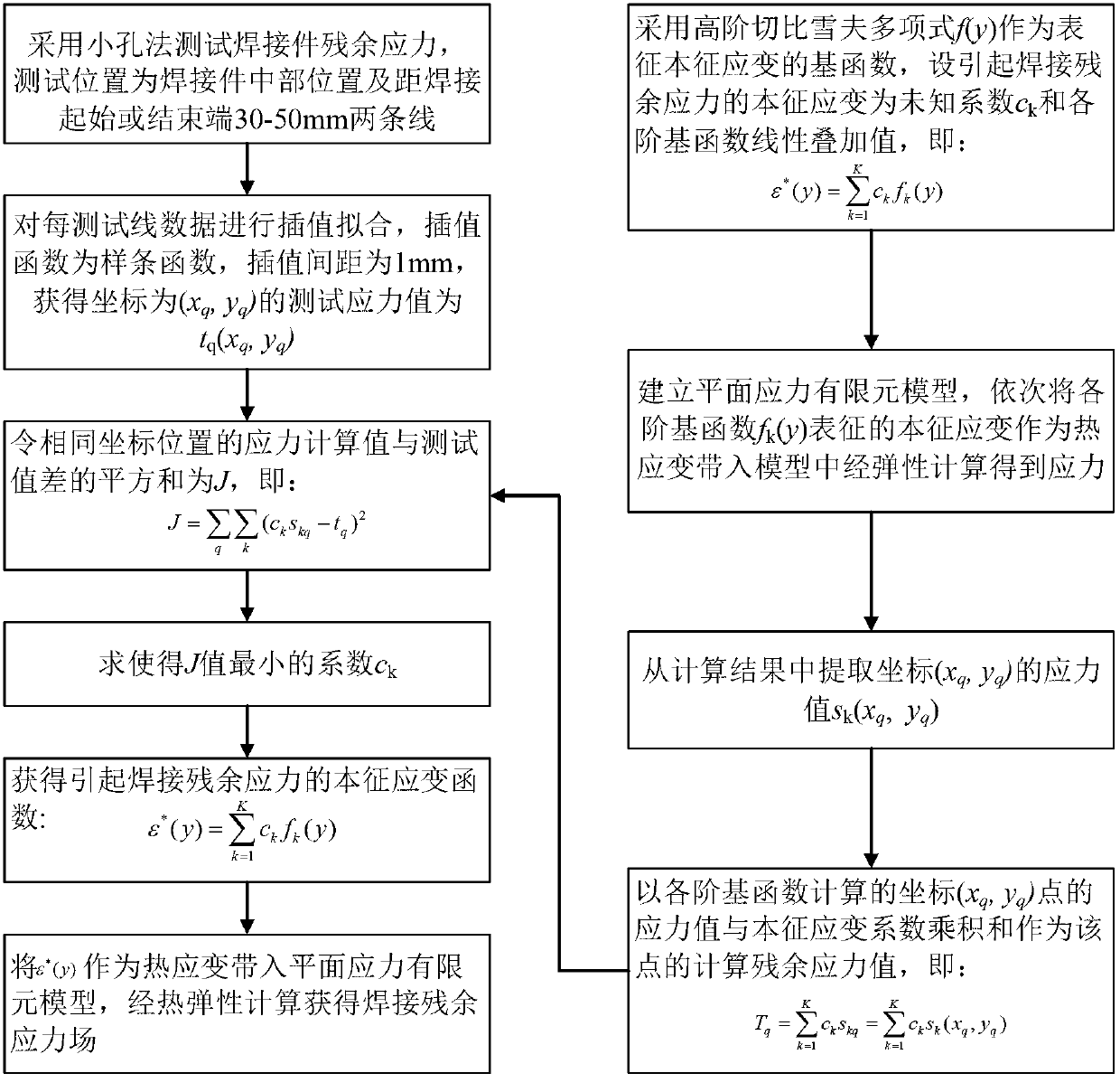
[0032] Such as figure 1 As shown, a method for constructing a thin plate welding residual stress field based on the test data of the small hole method includes the following steps:

[0033] (1) The small hole method is used to test the welding residual stress. The test position for the small hole method to test the welding residual stress is the middle position of the weldment and the position 30-50mm from the welding start or end, such as 35mm from the welding start or end. 40mm, 45mm, etc.; the measured point at each test position is required to reflect the stress change trend on a line perpendicular to the weld direction. The number of test points at each position is 5-15, for example, the number of test points can be 8, 10 , 12, etc.; perform interpolation fitting on the test data, the fitting function is a spline function, and the interpolation interval is 1mm;

[0034] (2) The high...


PUM


Abstract

The invention discloses a method for constructing a light gauge welding residual stress field on the basis of small-hole process tested data. The method comprises the following steps of: firstly, testing a residual stress of a weld assembly by adopting a small hole process, carrying out interpolation fitting on the tested stress values, then sequentially substituting each first-order polynomial in a finite element model by using a high-order Chebyshev polynomial as a primary function of representing unknown intrinsic strain causing the welding residual stress, carrying out calculation of elasticity to obtain calculated stress values of coordinate points with same tested stresses, selecting a coefficient enabling the quadratic sum of differences of the calculated stress values and the fitted tested stress values to be minimum as an intrinsic strain coefficient, multiplying the intrinsic strain coefficient by corresponding all order polynomials and then linearly overlapping to be used as an intrinsic strain, and finally obtaining a welding residual stress field through a finite element process. On the basis of the small hole process tested data, the intrinsic strain causing the welding residual stress is constructed by using a thermo-elasticity finite element method and a reverse analysis method, therefore, the distribution of the light gauge welding residual stress field is obtained; and the method is convenient to operate and high in efficiency.

Description

Technical field [0001] The invention relates to a method for testing residual stress field in the welding field, in particular to a method for constructing a thin plate welding residual stress field based on test data of a small hole method. Background technique [0002] At present, welding is a key technology for reliable, low-cost, and efficient connection of materials in the shipbuilding, nuclear power, petrochemical, aerospace, transportation, energy and other industries. However, welding will inevitably produce residual stress, which is an important factor leading to the failure of welded components (such as stress corrosion, fatigue strength and reduced service life). Therefore, accurate evaluation of it is the basis and basis for the failure evaluation and life evaluation of welded components. premise. [0003] Conventional welding residual stress evaluation can be divided into experimental measurement methods (such as small hole method, X-ray method and neutron diffraction...

Claims


Application Information

Patent Timeline
IPC IPC(8): G01N19/00
Inventor 刘川刘彬王俭辛胥国祥陈书锦胡庆贤
Owner JIANGSU UNIV OF SCI & TECH
Learn More