Test path selection method and corresponding wafer test method
A test path and wafer test technology, which is applied in the direction of semiconductor/solid-state device test/measurement, single semiconductor device test, etc., to shorten the test time, shorten the test path, and improve the test efficiency
- Summary
- Abstract
- Description
- Claims
- Application Information
AI Technical Summary
Problems solved by technology
Method used
Image
Examples
Embodiment 1
[0050] by Figure 7 shown in the flowchart as an example, combined with Figure 8 to Figure 11 , the test path selection method of the present invention will be described in detail. The test path selection method shown includes the following steps:
[0051] In step 1, a wafer is provided, the wafer being formed with dies, the dies comprising active dies and inactive dies.
[0052] In step 2, see Figure 8 , draw and form a wafer map according to the actual size of the wafer and the size and position of the die. The wafer map is divided into a plurality of squares, each of which represents a die. The position and size of each grid on the wafer map corresponds to the position and size of the dies of the wafer one-to-one, thus forming a wafer map corresponding to the dies of the wafer one-to-one.
[0053] In step 3, see Figure 8 , using a probe to identify the positions of valid dies and invalid dies of the wafer, the squares on the wafer map are marked with different patt...
Embodiment 2
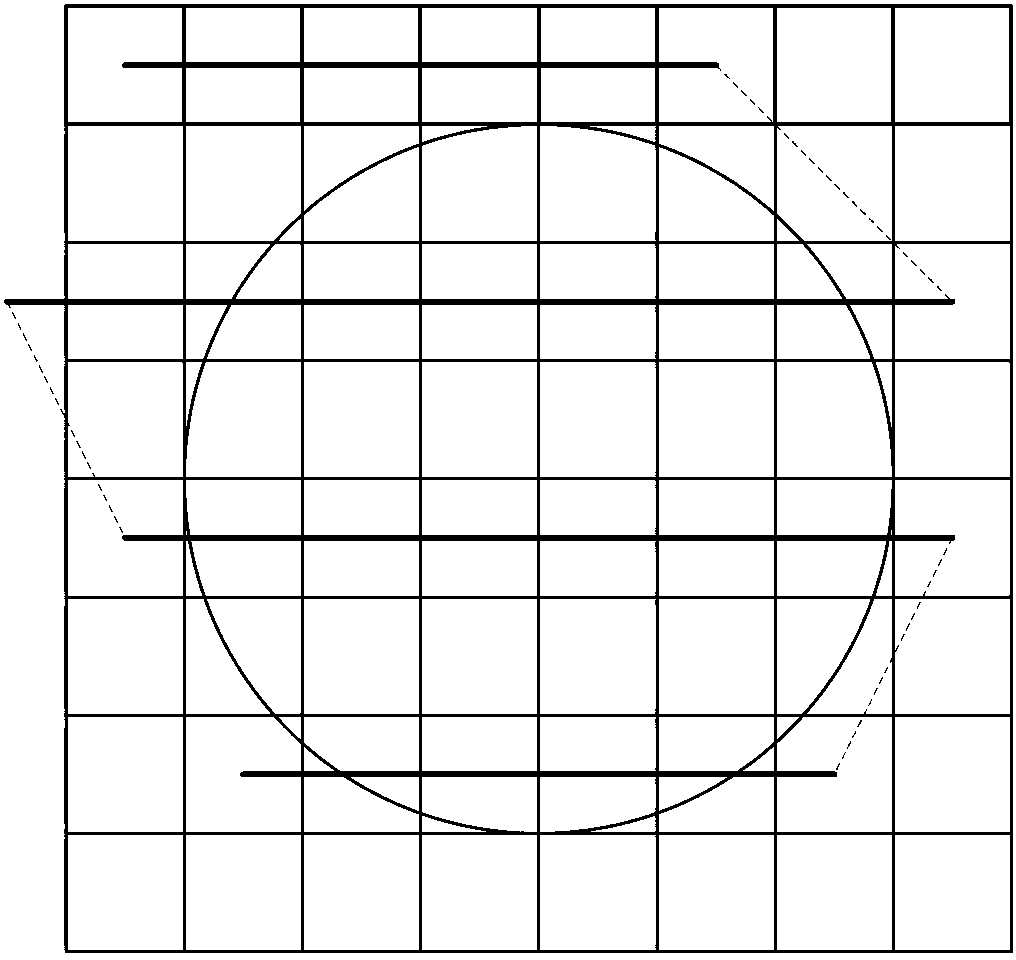
[0060] by Figure 7 shown in the flowchart as an example, combined with Figure 12 to Figure 14 , the test path selection method of the present invention will be described in detail. The test path selection method shown includes the following steps:
[0061] For Step 1 to Step 3, please refer to Step 1 to Step 3 in Embodiment 1, and details will not be repeated here.
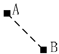
[0062] In step 4, a multi-circuit-block pin-card diagram is provided, and when the multi-circuit-block pin-card diagram is a pin-card diagram with three circuit blocks, that is, the multi-circuit-block pin-card diagram has the first pin-card mark, the second needle card mark and the third needle card mark, the straight path between the first needle card mark, the second needle card mark and the third needle card mark also forms a 0-180 degree angle with the horizontal direction angles, such as 90 degrees (see image 3 ).
[0063] According to the arrangement of the shapes and positions of the multi-circuit ...
Embodiment 3
[0068] by Figure 7 shown in the flowchart as an example, combined with Figure 15 to Figure 17 , the test path selection method of the present invention will be described in detail. The test path selection method shown includes the following steps:
[0069] For Step 1 to Step 3, please refer to Step 1 to Step 3 in Embodiment 1, and details will not be repeated here.
[0070] In step 4, a multi-circuit-block pin-card diagram is provided, and when the multi-circuit-block pin-card diagram is a pin-card diagram with 4 circuit blocks, that is, the multi-circuit-block pin-card diagram has the first pin-card mark, the second needle card mark, the third needle card mark and the fourth needle card mark, the straight path between the first needle card mark, the second needle card mark, the third needle card mark and the fourth needle card mark Also arranged at an angle of 0-180 degrees to the horizontal (see Figure 5 ), the angle is 45 degrees as an example for illustration.
[0...
PUM
 Abstract
Description
Claims
Application Information
 - R&D
- Intellectual Property
- Life Sciences
- Materials
- Tech Scout
- Unparalleled Data Quality
- Higher Quality Content
- 60% Fewer Hallucinations
Browse by: Latest US Patents, China's latest patents, Technical Efficacy Thesaurus, Application Domain, Technology Topic, Popular Technical Reports.
© 2025 PatSnap. All rights reserved.Legal|Privacy policy|Modern Slavery Act Transparency Statement|Sitemap|About US| Contact US: help@patsnap.com


