
256-grating light head device

A light head and grating technology, which is applied in the field of 256 grating light head devices, can solve the problems of limited range of use and plate making speed, low mass production yield, and inability to move continuously, achieving fast modulation response speed, mature production technology, and easy operation. The effect of mass production use

Active Publication Date: 2013-10-09
AMSKY TECHNOLOGY CO LTD
View PDF7 Cites 1 Cited by
  • Summary
  • Abstract
  • Description
  • Claims
  • Application Information

AI Technical Summary

Problems solved by technology

Because this technology uses a two-dimensional modulation device, it cannot move continuously during actual work. It needs to precisely control the amount of movement, like stamping a stamp, and image the pattern on the plate piece by piece in the form of stamping. This device is severely limited. Due to the range of its use and the speed of plate making, the CTP using the DMD packaging device cannot be made into the common external drum type and internal drum type, and can only use the most primitive flat type CTP method; at the same time, the response frequency of DMD usually does not exceed several hundred Hz , which is very different from the millions of hertz required in plate making, which also greatly limits its plate making speed
[0007] The devices in the above patents all require special customization, and due to the high manufacturing difficulty, the mass production yield has not been high

Method used


Image

  • 256-grating light head device
  • 256-grating light head device
  • 256-grating light head device

Examples


Embodiment Construction

[0027] In order to make the implementation technical means, creative features, objectives and effects of the present invention easy to understand, the present invention will be further elaborated below in conjunction with specific illustrations.

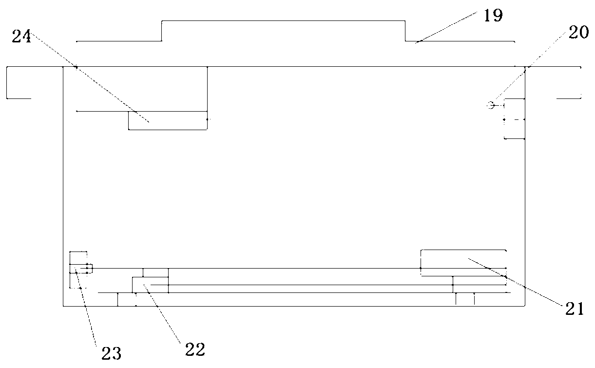
[0028] A 256 grating optical head device, comprising: a housing 19, a position adjustment mechanism 20, a transducer module 21, a reflection diaphragm 22, a mirror module 23, a laser module 24, the mirror module 23 is located at one end of the housing 19, The other end of the housing 19 is provided with a transducer module 21, a reflective aperture 22 is provided between the transducer module 21 and the mirror module 23, a laser module 24 is provided at one end of the upper part of the housing 19, and a position adjustment mechanism is provided at the other end 20.

[0029] The laser module 24 includes: a laser, a fast axis, a slow axis, and a collimating lens.

[0030] The transducer module 21 includes: an acousto-optic modulator, ...


PUM


Abstract

The invention discloses a 256-grating light head device. The 256-grating light head device comprises a shell, a position regulation mechanism, a transducer module, a reflecting diaphragm, a reflecting mirror module and a laser module, wherein the reflecting mirror module is positioned at one end of the shell; the transducer module is arranged at the other end of the shell; the reflecting diaphragm is arranged between the transducer module and the reflecting mirror module; the laser module is arranged at one end of the upper part of the shell; the position regulation mechanism is arranged at the other end of the upper part of the shell. The response frequency of a modulator exceeds 10MHz, and the modulator is controlled by using ultrasonic waves. Compared with a device such as a grating light valve (GLV), the modulator has the advantages that a switch response speed exceeds over 10 times; ideal square light spots can be accurately generated. An ultrasonic acousto-optic modulator is applied to the industries of communication and the like for dozens of years, and is mature in production process, low in manufacturing cost and suitable for batch production.

Description

technical field [0001] The invention relates to the field of laser imaging, in particular to a 256 grating optical head device. Background technique [0002] The grating optical head of traditional fiber optic technology uses 32, 48 or 64 lasers with a power of 1W as the light source, which are coupled to the imaging lens through a corresponding number of close-packed optical fibers. This method uses a large number of lasers, is expensive, and the laser circuit The number is limited by optical fiber technology, and it can only achieve 64 channels at most. Optical fiber technology grating optical head plate making, not only the stability of plate making is low, but also can not print FM network, the quality of dots is limited, and high-quality printing plates cannot be printed. [0003] In the field of CTP, the technology that can realize more than 64 plate-making technologies currently has patents only the VCSEL technology (CN 1497272A) of Kodak Company of the United States...

Claims


Application Information

Patent Timeline
Patent Type & Authority Applications(China)
IPC IPC(8): G03G15/04
Inventor 唐晖李兵涛
Owner AMSKY TECHNOLOGY CO LTD
Learn More