Cavity lining of plasma etching equipment

An etching equipment and plasma technology, applied in the field of chamber lining, can solve the problems of chamber pollution, damage, poor uniformity, etc., and achieve the effects of large area, improved uniformity, and maintenance of purity

Inactive Publication Date: 2013-10-09
TDG MACHINERY TECH
View PDF6 Cites 9 Cited by
  • Summary
  • Abstract
  • Description
  • Claims
  • Application Information

AI Technical Summary

Problems solved by technology

[0006] In order to overcome the shortcomings of the poor uniformity of the etching gas in the reaction chamber of the existing plasma etching equipment and the disadvantages of easily causing chamber pollution and damage, the present invention provides a plasma etching equipment capable of uniformly reacting the etching gas in the chamber chamber lining

Method used


Image

  • Cavity lining of plasma etching equipment
  • Cavity lining of plasma etching equipment
  • Cavity lining of plasma etching equipment

Examples


Embodiment Construction

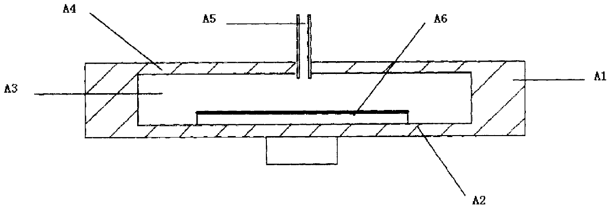
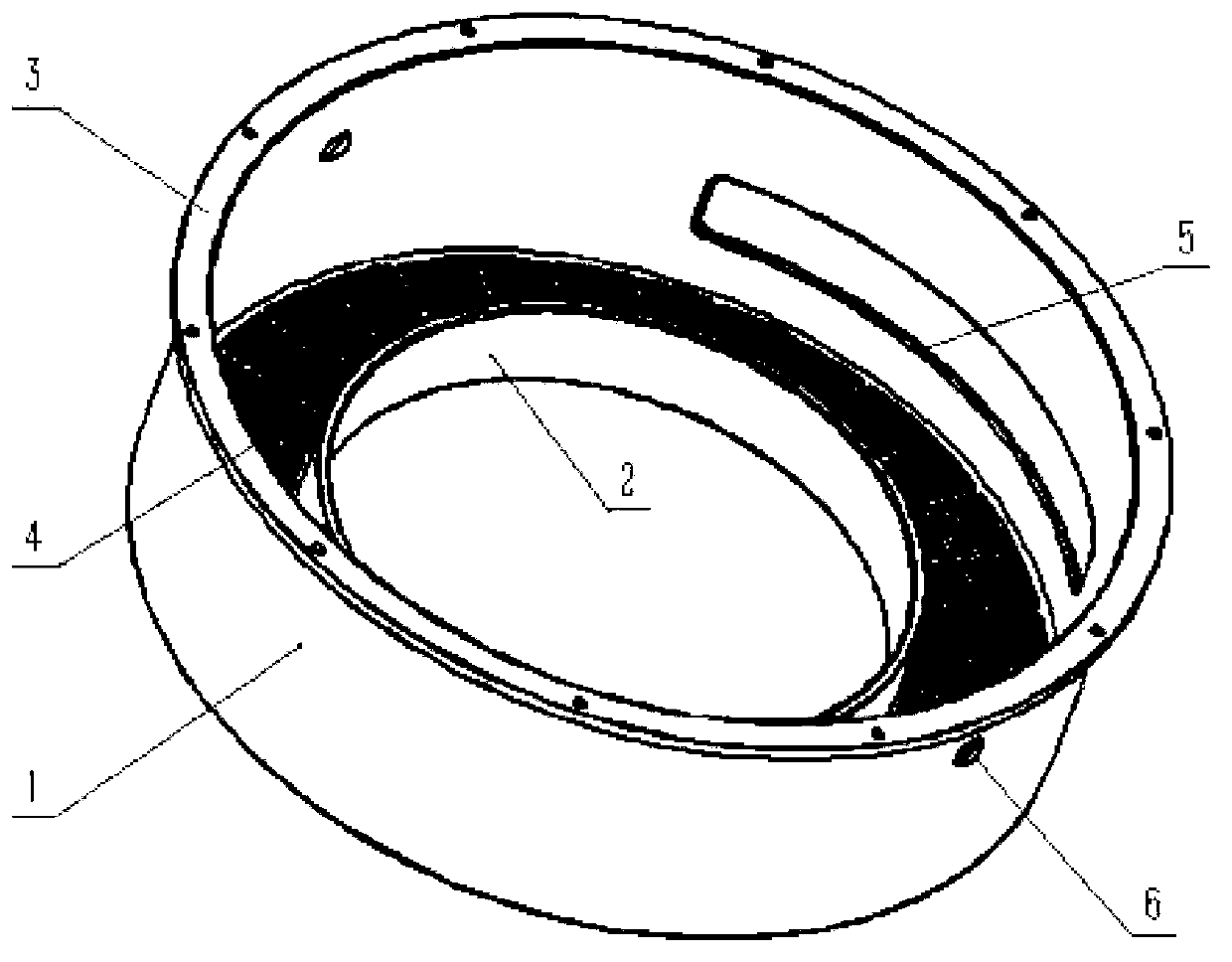
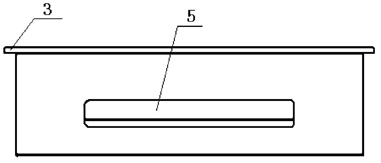
[0020] like Figure 2-5 As shown, the chamber lining of the plasma etching equipment includes a cylindrical body 1, which is provided with a conveying sheet opening 5 for picking up and sending wafers to be etched, and the outer wall of the body 1 and the reaction chamber of the plasma etching equipment The chamber 7 is adapted, and the bottom of the body 1 is provided with a ring-shaped bottom plate 2 extending inward. The ring-shaped bottom plate 2 matches the position of the wafer 9 to be etched. There is a fixed flange 3 connected to the reaction chamber 7 . The position matching of the annular bottom plate 2 and the wafer 9 to be etched refers to that the top surface of the annular bottom plate 2 is flush with the wafer 9 to be etched.

[0021] One side of the reaction chamber 7 is provided with a vacuum chamber 8, the inner substrate separates the reaction chamber 7 and the vacuum chamber 8, and the vacuum chamber 8 is connected with a vacuum pump.

[0022] The even fl...


PUM


Abstract

A cavity lining of plasma etching equipment comprises a cylindrical body. A wafer-conveying opening is formed in the body and used for taking and conveying a wafer to be etched. The outer wall of the body is matched with a reaction cavity of the plasma etching equipment. A circle of annular base plate is arranged at the bottom of the body and extends inward. The annular base plate is matched with the wafer to be etched in positions, and flow-evening slotted holes are evenly distributed in the annular base plate. A fixing flange is arranged at the top of the body and connected with the reaction cavity. The cavity lining of the plasma etching equipment has the advantages of being capable of evenly reacting etching gas in the reaction cavity and good in purity in the reaction cavity and service life of the reaction cavity is long.

Description

technical field [0001] The invention relates to the technical field of plasma etching, in particular to a chamber lining of dry plasma etching equipment. Background technique [0002] Etching is an important process in the manufacturing process of semiconductors, microelectronics and LEDs. Etching is the process of selectively removing unnecessary materials from the surface of silicon wafers or sapphire substrates by chemical or physical methods. With the improvement of the integration level of semiconductor devices, the line width of semiconductor devices is getting smaller and smaller, the control of critical dimensions is becoming more and more important, and the requirements for etching processes are also getting higher and higher. In terms of process, etching can be divided into wet etching and dry etching. Dry etching is plasma etching. Usually, an etching gas is introduced into a plasma processing device, and the etching gas is ionized to form a plasma, and the wafer...

Claims


Application Information

Patent Timeline
Patent Type & Authority Applications(China)
IPC IPC(8): H01J37/32H01L21/67
Inventor 张钦亮平志韩苏静洪王谟祝启蒙
Owner TDG MACHINERY TECH
Why Eureka
Try Eureka