Short-circuit protection structure

A technology for short-circuit protection and control circuits, which is applied in the direction of emergency protection circuit devices, circuits, and protection against overcurrent, which can solve problems such as chip pin short-circuit, damage, and output-stage transistor damage, and improve product reliability. , the protection structure is simple and the cost advantage is obvious

Inactive Publication Date: 2013-10-09
SUZHOU POWERON IC DESIGN
View PDF5 Cites 0 Cited by
  • Summary
  • Abstract
  • Description
  • Claims
  • Application Information

AI Technical Summary

Problems solved by technology

However, when the sampling resistor Rs1 is not integrated with the control circuit 1 or the output stage transistor 2, the short circuit problem of the sampling resistor Rs1 introduced in the actual production process becomes inevitable. PCB connection strips, short circuit of chip pins, etc.
[0003] When Rs1 is short-circuited, the resistance value becomes very small, Vs1 cannot reach the reference voltage Vref1 of the internal comparator, the control circuit will fail the over-current protection (OCP) of the output stage transistor, the output stage transistor will work at the maximum duty cycle, and the transistor It will work in the saturation region (high Vds and large Ids), beyond its own safe working area, and eventually cause damage to the output stage transistor, and in severe cases, it will cause damage to the entire system

Method used


Image

  • Short-circuit protection structure
  • Short-circuit protection structure
  • Short-circuit protection structure

Examples


Embodiment Construction

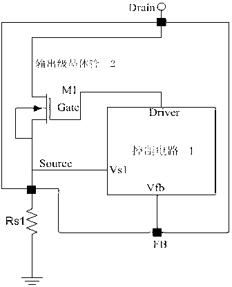
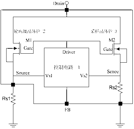
[0030] Such as image 3 As shown, the short circuit protection circuit structure includes an output stage transistor 2 (M1), and its current sampling resistor (Rs1); a sampling transistor 3 (M2) whose size is much smaller than the output stage transistor 2, and its current sampling resistor (Rs2) ; a control circuit 1 . Among them, the output stage transistor 2 (M1) is used as the circuit output stage power switch, the control circuit 1 controls the switching time length and duty cycle of the output stage transistor 2 and the sampling transistor 3, and the drain terminal of the output stage transistor 2 is connected to the drain of the sampling transistor 3 terminal, the source terminal of the output stage transistor 2 is connected to a sampling resistor (Rs1), the source terminal of the sampling transistor 3 is connected to another sampling resistor (Rs2), the gate terminal of the output stage transistor 2 is connected to the gate terminal of the sampling transistor 3 and is ...


PUM


Abstract

The invention relates to a short-circuit protection structure which comprises a first transistor, a second transistor, a control circuit, a first transistor current sampling resistor and a second transistor current sampling resistor. The control circuit controls the on-off time duration and the duty ratio of the first transistor and the second transistor. The drain terminal of the first transistor is connected with the drain terminal of the second transistor. The source terminal of the first transistor is connected with one sampling resistor, and the source terminal of the second transistor is connected with the other sampling resistor. The gate terminal of the first transistor is connected with the gate terminal of the second transistor and a driving stage of the control circuit. The first transistor and the second transistor are high-voltage transistors, the size of the second transistor is smaller than that of the first transistor, and the second transistor samples currents of the first transistor. The structure can effectively protect output stage transistors in a power source system and avoid the situation that due to the fact that the current sampling resistors are short-circuited, chips or components and parts of a system are damaged.

Description

technical field [0001] The invention relates to a short-circuit protection structure suitable for power management integrated circuits, belonging to the technical field of power semiconductors. Background technique [0002] Traditional switching power chip structure such as figure 1 As shown, it consists of control circuit 1 and output stage transistor 2. The control circuit 1 samples the voltage Vs1 on the resistor Rs1 and the system-level feedback Vfb, controls the turn-on time length and duty cycle of the output-stage transistor 2 through an internal loop algorithm, and finally realizes stable voltage and current output of the system. Regardless of whether the output stage transistor 2 is integrated with the control circuit 1 or not, the sampling resistor Rs1 is usually not integrated with the chip, so that a more stable sampling current can be achieved, because the temperature characteristics and production of the external resistor on the chip Batch stability is signif...

Claims


Application Information

Patent Timeline
Patent Type & Authority Applications(China)
IPC IPC(8): H02H7/20H02H3/08H01L27/02
CPCH02H3/087H02H9/025H03K17/0822
Inventor 陶平李海松庄华龙易扬波
Owner SUZHOU POWERON IC DESIGN
Why Eureka
Try Eureka