Popping candy producing equipment

A production equipment and popping candy technology, which is applied in confectionery, confectionary industry, food science, etc., can solve problems such as poor cooling effect, low puffing efficiency, and insufficient pressure, so as to improve production efficiency, improve syrup quality, and avoid blocking effect

Active Publication Date: 2013-10-16
汕头市茂发食品有限公司
View PDF4 Cites 3 Cited by
  • Summary
  • Abstract
  • Description
  • Claims
  • Application Information

AI Technical Summary

Problems solved by technology

[0005] Although the above-mentioned expansion tank can achieve the purpose of expansion, there are still great defects: 1. Since the molten syrup is accumulated in the lower part of the tank body, the cooling of the molten syrup by the cooling water is only limited to the contact part between the molten syrup and the inner wall of the tank body, And cooling water can only pass through the mode of gradual infiltration to the cooling of the middle part of molten syrup, and cooling effect is very poor, and solidification rate is very slow; The middle part is difficult to puff, and the puffing efficiency is low. After crushing, it will become a finished popping candy, which has a poor taste; 3. It cannot be broken naturally, and another process is required for crushing; 4. It needs to wait for the molten syrup in the tank to completely solidify , After decompression, puffing and discharge, the next injection of molten syrup can be performed. The waiting time is very long, continuous production cannot be realized, and the production efficiency is low.
[0006] In addition, sugar melting and boiling sugar are both completed in the sugar cooking pot of the sugar cooking device. Since the temperature requirements for sugar melting and boiling sugar are different, sugar melting requires a lower temperature to avoid uneven heating of white granulated sugar and maltose blocks. And cause scorching phenomenon, and above-mentioned sugar boiling device is carried out in the same sugar boiling pot owing to melting sugar, boiling sugar, is difficult to control temperature respectively, causes scorching phenomenon easily, or the white granulated sugar, maltose block etc. do not melt completely, cause The quality of the syrup decreases, which ultimately affects the quality of the confectionery
And because the popping candy has the characteristics of melting at the entrance, the requirements for the syrup are more stringent, therefore, the above-mentioned sugar boiling pot cannot meet the boiling sugar requirements of the popping candy; Pour out the syrup that has been boiled in the sugar pot completely, and then the next pot of sugar can be melted and boiled, and the sugar can not be boiled continuously, and the production efficiency is low
[0007] In addition, the carbon dioxide supply device has the following two disadvantages: 1. The carbon dioxide vaporized by the vaporizer is directly passed into the stirring tank, the pressure of the carbon dioxide is not enough, and the carbon dioxide is difficult to integrate into the molten syrup, resulting in the carbon dioxide content in the finished popping candy 2. The temperature of carbon dioxide vaporized by the vaporizer is low (generally close to 0°C), while the temperature of molten syrup is high (generally higher than 100°C), and the temperature difference between the two is very large. After being in contact with a certain part of the syrup, the contact part cools down rapidly to produce local solidification, which prevents the continuous incorporation of carbon dioxide. On the one hand, the carbon dioxide content in the finished popping candy is low and the taste is poor. On the other hand, the finished popping candy results in carbon dioxide The distribution of carbon dioxide is not uniform enough, and the taste is also poor, which leads to poor quality of popping candy

Method used


Image

  • Popping candy producing equipment
  • Popping candy producing equipment
  • Popping candy producing equipment

Examples


Embodiment Construction

[0040] Further description will be given below in conjunction with the accompanying drawings and preferred embodiments of the present invention.

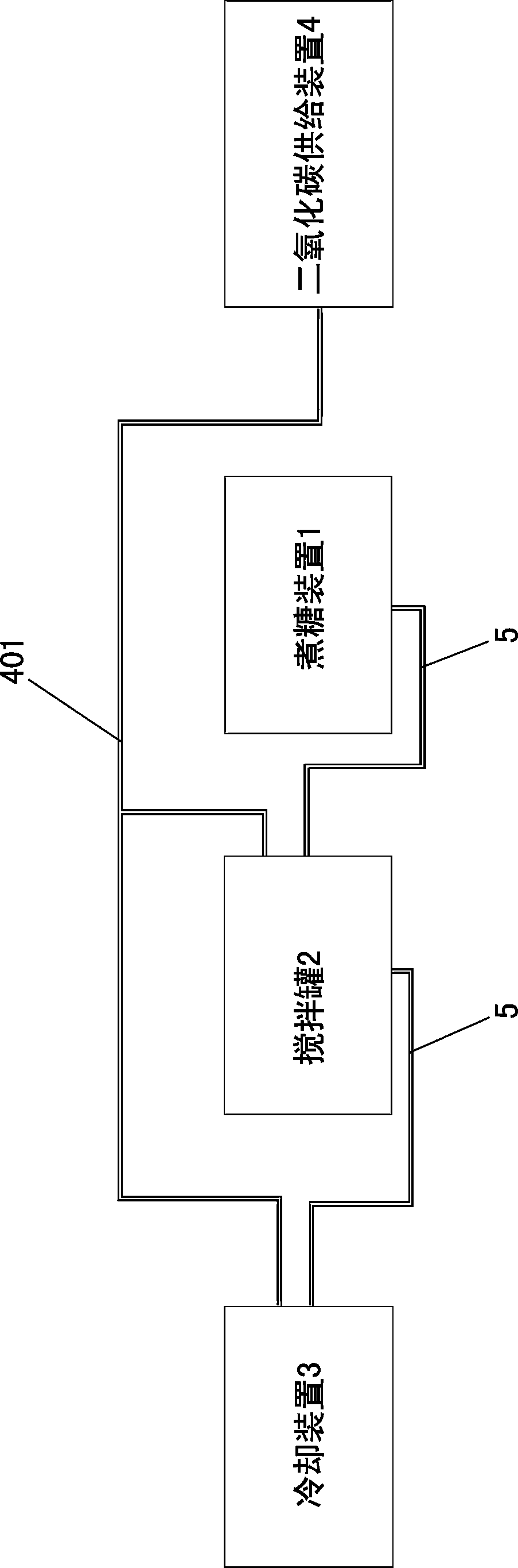
[0041] like figure 1 As shown, this kind of popping candy production equipment includes a sugar cooking device 1, a stirring tank 2 and a cooling device 3 arranged in sequence, and a carbon dioxide supply device 4 connected with the stirring tank 2 and the cooling device 3.

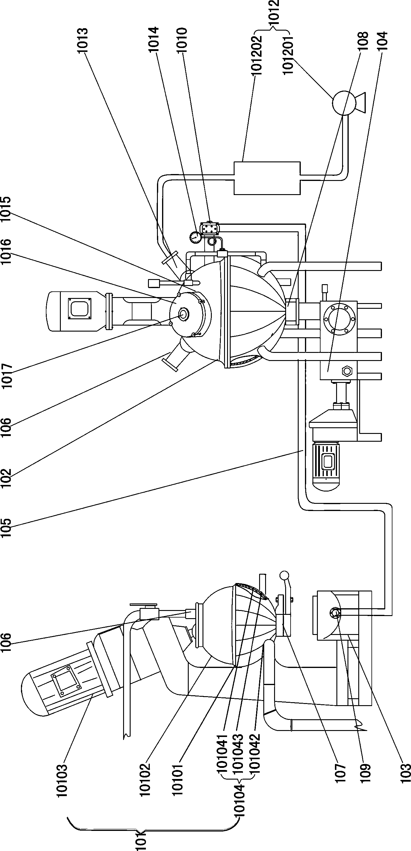
[0042] like figure 2 As shown, the sugar cooking device 1 includes a sugar melting pot 101, a sugar boiling pot 102, a storage barrel 103, a syrup extraction device 104 (usually a pump) and a sugar feeding pipe 105. The bottom of the sugar melting pot 101 is provided with a discharge valve 107, The storage barrel 103 is arranged below the discharge valve 107, the bottom of the sugar cooking pot 102 is provided with a syrup outlet 108, the syrup extraction device 104 is connected with the syrup outlet 108, the storage barrel 103 is provided with a sugar outlet...


PUM


Abstract

The invention relates to popping candy producing equipment which comprises a sugar boiling device, a stirring pot and a cooling device, arranged in sequence, as well as a carbon dioxide feeding device connected with the stirring pot, wherein the sugar boiling device is divided into a sugar melting part and a sugar boiling part, and independent temperature control is carried out on the two parts to improve the syrup quality; the stirring pot adopts a heat preservation structure to prevent the melting syrup in the stirring pot body from coagulating and solidifying, more carbon dioxide is enabled to be mixed in the melting syrup, and the taste of the popping candy is enabled to be better; the cooling device adopts a strip-shaped pipe body as a puffing cavity to supply carbon dioxide during the puffing process, the puffing is enabled to be more thorough, the carbon dioxide content in the popping candy finished product is enabled to be higher, and the taste is better; through the arrangement of a carbon dioxide heating device, the carbon dioxide feeding device avoids the part solidification of syrup, and prevents the carbon dioxide from continuously blending, thereby enabling the popping candy finished product to be higher in carbon dioxide content, more uniform in distribution and better in taste, and further improving the quality of the popping candy.

Description

technical field [0001] The invention relates to a candy production equipment, in particular to a popping candy production equipment. Background technique [0002] Popping candy is a favorite food for people, especially children. Its principle is to fill the candy with carbon dioxide (or other gases) and combine it with the candy during the process of making candy. When eating, the saliva moistens and contains a lot of carbon dioxide The carbon dioxide that has lost its binding force escapes continuously, making the candy in the mouth constantly beating, giving people a sense of freshness. [0003] At present, popping candy production equipment generally includes a sugar cooking device, a stirring tank, an expanding tank (cooling device) and a carbon dioxide supply device. The carbon dioxide supply device is connected to the stirring tank, and the molten syrup is filled with high-pressure carbon dioxide during the stirring process. Carbon dioxide is mixed into the molten syr...

Claims


Application Information

Patent Timeline
Patent Type & Authority Applications(China)
IPC IPC(8): A23G3/02
Inventor 陈旭斌
Owner 汕头市茂发食品有限公司
Why Eureka
Try Eureka