Optimized design method of reducing sonic system sound insulator of acoustic logging-while-drilling drill collar

A design method and an optimized technology, applied in surveying, earthwork drilling, wellbore/well components, etc., can solve the problems of unfavorable drilling sonic technology promotion and use, high cost, high R&D and processing costs, etc.

Active Publication Date: 2013-10-16
CHINA UNIV OF PETROLEUM (EAST CHINA)
View PDF8 Cites 5 Cited by
  • Summary
  • Abstract
  • Description
  • Claims
  • Application Information

AI Technical Summary

Problems solved by technology

[0004] Most of the existing sonic while drilling technology adopts grooves on the drill collar for sound insulation. The high cost of well logging is not conducive to the promotion and use of acoustic wave technology while drilling

Method used


Image

  • Optimized design method of reducing sonic system sound insulator of acoustic logging-while-drilling drill collar
  • Optimized design method of reducing sonic system sound insulator of acoustic logging-while-drilling drill collar
  • Optimized design method of reducing sonic system sound insulator of acoustic logging-while-drilling drill collar

Examples


Embodiment 1

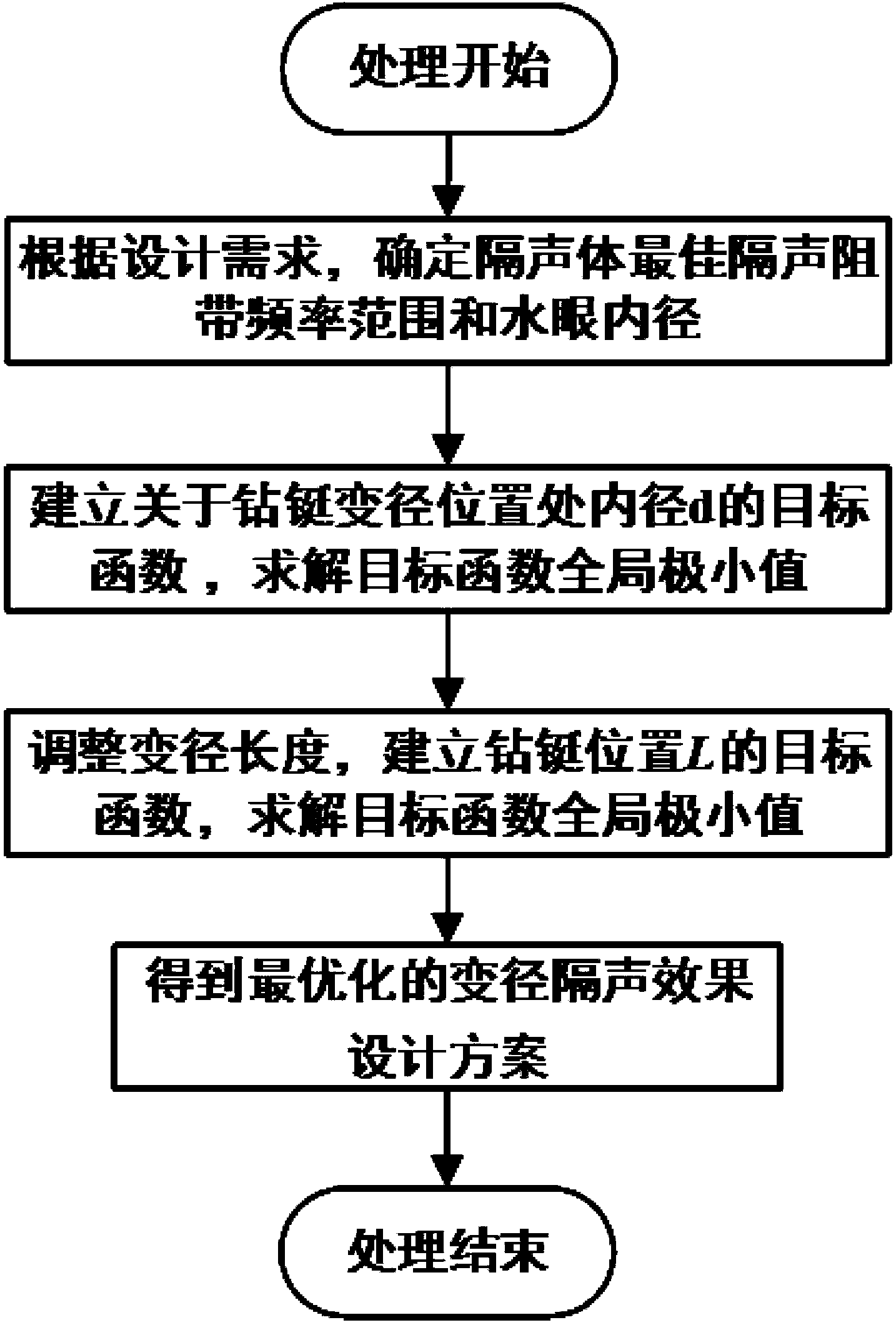
[0064] The optimal design method for the sound insulation of the sound system of the diameter-changing acoustic logging-while-drilling drill collar, such as figure 1 shown, including the following steps:

[0065] Step 1. According to the design requirements, determine the frequency range of the optimal sound insulation stop band of the sound insulation body and the inner diameter of the water hole

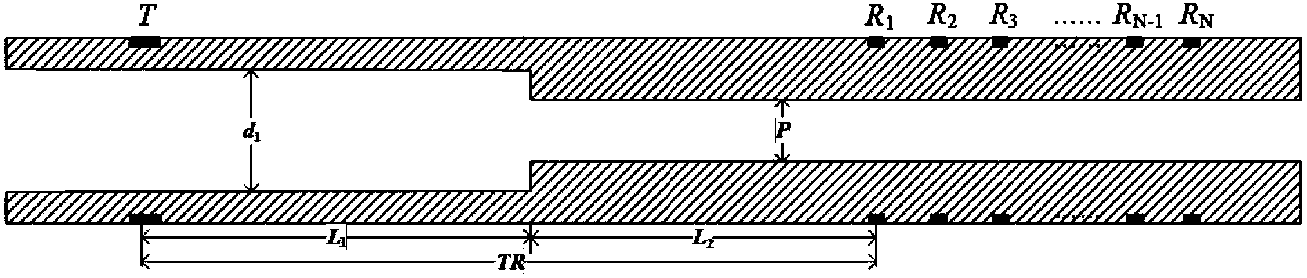
[0066] Figure 2a Transmitting sound source transducer T and receiving transducer R are shown 1 , R 2 , R 3 、...R N-1 , R N Schematic diagram of the sound system for a diameter change. The inner diameter of the drill collar from the transmitting sound source transducer T to the receiving transducer is d 1 and P, starting from the emitting sound source transducer T, the variable diameter lengths are L respectively 1 and L 2 , T in the figure is the transmitting sound source transducer, and the receiving transducer array is N, respectively R 1 , R 2 , R 3 、...R N-1 , R ...

Embodiment 2

[0080] The optimal design method for the sound insulation of the sound system of the reduced-diameter acoustic logging-while-drilling drill collar with secondary diameter reduction, such as figure 1 shown, including the following steps:

[0081] Step 1. According to the design requirements, determine the frequency range of the sound insulation body's optimal sound insulation stop band and the inner diameter of the water hole.

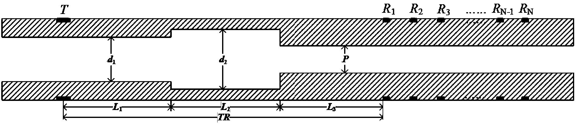
[0082] Figure 2b Shown is a schematic diagram of the acoustic system of the secondary diameter reduction between the transmitting sound source transducer T and the receiving transducer, and the inner diameters of the drill collars from the transmitting sound source transducer T to the receiving transducer array are respectively d 1 、d 2 and P, starting from the emitting sound source transducer T, the variable diameter lengths are L respectively 1 , L 2 and L 3 , T in the figure is the transmitting sound source transducer, and the receiving transdu...

Embodiment 3

[0096] The optimal design method for the sound insulation of the sound system of the variable-diameter sound system of the acoustic logging-while-drilling drill collar with three times of diameter reduction, such as figure 1 shown, including the following steps:

[0097] Step 1. According to the design requirements, determine the frequency range of the optimal sound insulation stop band of the sound insulation body, the wall thickness of the drill collar and the inner diameter of the water hole

[0098] Figure 2c Shown is a schematic diagram of the sound system of a diameter change between the transmitting sound source transducer T and the receiving transducer, and the inner diameters of the drill collars from the transmitting sound source transducer T to the receiving transducer are respectively d 1 、d 3 、d 2 and P, starting from the emitting sound source transducer T, the variable diameter lengths are L respectively 1 , L 2 , L 3 and L 4 , T in the figure is the tran...


PUM


Abstract

The invention belongs to the field of applied geophysics/acoustic logging and relates to an optimized design method of a reducing sonic system sound insulator of an acoustic logging-while-drilling drill collar. The optimized design method of the reducing sonic system sound insulator of the acoustic logging-while-drilling drill collar comprises the following steps of: step 1, determining an optimal sound insulation resistance band frequency range of the sound insulator and an inner diameter of a water hole according to the design requirement; step 2, establishing a target function of the inner diameter of a reducing position of the drill collar, solving an overall situation minimal value of the target function and determining the optimized inner diameter; and step 3, further adjusting the combination of reducing lengths and establishing a target function; and solving an overall situation minimal value of the target function and determining the optimized combination of the reducing lengths. According to the optimized design method disclosed by the invention, the machining difficulty and cost are reduced and the mechanical strength of the drill collar is enhanced; the problems that a sound insulation effect of an etching groove sound insulator is controlled by a plurality of parameters including a groove width, a groove depth, a groove distance, the quantity of etching grooves and the like, the method only can be designed by experiences and a numerical simulation method and an optimize etching groove structure is difficult to find can be avoided.

Description

technical field [0001] The invention belongs to the field of applied geophysics / acoustic well logging, and in particular relates to an optimal design method of a variable-diameter sound insulation body of a drill collar for acoustic logging while drilling. Background technique [0002] The purpose of sonic logging while drilling is to determine the formation compressional wave velocity and shear wave velocity during the drilling process, and provide important information for the exploration and development of oil and gas fields. For example, by combining the measured elastic wave velocity model with seismic exploration data, the position of the formation interface can be determined in real time, and the formation pore pressure can be estimated. The conventional wireline sonic logging can be replaced by sonic logging while drilling, and a lot of derrick occupancy time can be saved, which is especially important in deep sea drilling. [0003] One of the key technologies of so...

Claims


Application Information

Patent Timeline
Patent Type & Authority Applications(China)
IPC IPC(8): E21B47/14E21B49/00
Inventor 苏远大唐晓明庄春喜黑创
Owner CHINA UNIV OF PETROLEUM (EAST CHINA)
Why Eureka
Try Eureka