
Split solar device with U-shaped tube heat collector and detachable heat exchanger

A heat collector and heat exchanger technology, applied in the field of split solar energy, can solve problems such as not suitable for cold regions, low thermal efficiency, fatigue crack leakage, etc., to improve heat exchange efficiency and anti-corrosion performance, and improve heat exchange efficiency , the effect of improving the service life

Inactive Publication Date: 2013-10-16
威海澳华新能源有限公司
View PDF0 Cites 0 Cited by
  • Summary
  • Abstract
  • Description
  • Claims
  • Application Information

AI Technical Summary

Problems solved by technology

The heat collection efficiency of the vacuum heat pipe collector is high, but the vacuum degree gradually decreases with the increase of the service life, so that the heat collection efficiency is insufficient. The heat loss of the flat plate collector is large and it is not suitable for cold regions, and the overall thermal efficiency is not high.
U-shaped tubes are generally made of copper tubes. Although copper has a high thermal conductivity, copper tubes are easy to open when welding, and copper is easy to oxidize, and it is easy to block circulation pipes. Copper has low tensile strength and is prone to fatigue cracks and medium leakage. question

Method used


Image

  • Split solar device with U-shaped tube heat collector and detachable heat exchanger
  • Split solar device with U-shaped tube heat collector and detachable heat exchanger

Examples


Embodiment Construction

[0013] The present invention will be further described below in conjunction with accompanying drawing:

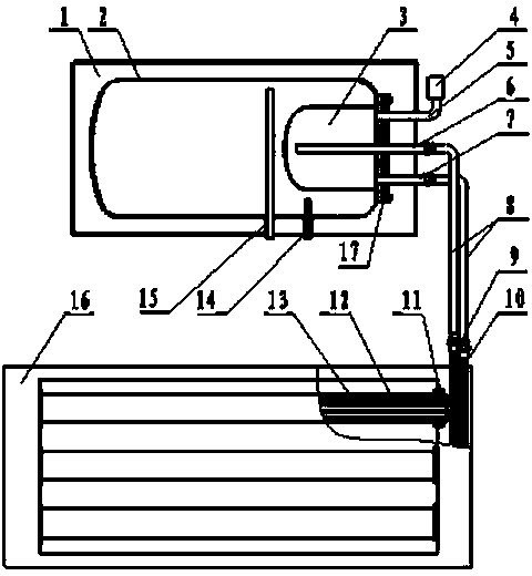
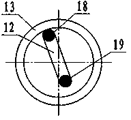
[0014] Such as figure 1 As shown, the present invention relates to a split solar energy with a U-shaped tube heat collector and a detachable heat exchanger. Heater 3 and heat exchanger 3 are provided with exhaust port 4, medium circulation inlet 6 and medium circulation outlet 7 respectively, exhaust port 4 is connected to exhaust valve 5, medium circulation inlet 6 and medium circulation outlet 7 pass through The outer wall of the water tank 1 is connected to the medium circulation pipe 8, and the inner tank 2 is provided with a water inlet pipe 14 and an outlet pipe 15, and the water inlet pipe 14 and the water outlet pipe 15 pass through the water tank 1 and are connected to the external pipe; 13 is connected to the heat collector frame 16 through the seal ring 11, the vacuum tube 13 is inserted with a stainless steel U-shaped tube 12, and the two ends of the U-shap...


PUM


Abstract

The invention relates to a split solar device with a U-shaped tube heat collector and a detachable heat exchanger. The split solar device comprises a water tank and the heat collector, and is characterized in that an inner container is arranged in the water tank, the detachable heat exchanger is arranged in the inner container, an exhaust port, a medium circulation inlet and a medium circulation outlet are formed in the outer end of the heat exchanger, the exhaust port is connected to an exhaust valve, the medium circulation inlet and the medium circulation outlet penetrate the outer wall of the water tank and are connected to a medium circulation pipeline, the inner container is provided with a water inlet pipe and a water outlet pipe, and the water inlet pipe and the water outlet pipe penetrate the water tank and are connected to an external pipeline; a vacuum pipe is arranged in a heat collector frame, and is connected to the heat collector frame through a seal ring, a U-shaped stainless steel pipe is inserted into the vacuum pipe, the upper part of the U-shaped pipe is a heat pipe part, the lower part of the U-shaped pipe is a cold pipe part, and the two ends of the U-shaped pipe are respectively connected to a medium heat collection outlet and a medium heat collection inlet which are respectively connected to the medium circulation inlet and the medium circulation outlet of the water tank to form a circulation loop. According to the invention, the U-shaped pipe is additionally arranged and filled with medium, and the vacuum pipe can avoid water leakage and fouling, so that the heat collection efficiency of the split solar device can not be affected even in a long-term use process.

Description

technical field [0001] The invention relates to the field of solar water heaters, and relates to the split solar energy of a U-shaped tube heat collector and a detachable heat exchanger. Background technique [0002] At present, most of the water tanks of split solar water heaters adopt a pressure-bearing structure, and the heat exchange structure is divided into built-in heat exchange and external heat exchange. Most of the built-in heat exchangers are welded structures. Although the thermal efficiency is improved, the welds are easy to corrode due to high pressure and high heat, causing the medium to leak out and pollute the water tank; the external heat exchanger has a large heat transfer area, and the heat exchanger does not bear external pressure. , but the interlayer is difficult to enamel, making it difficult to guarantee the anti-corrosion performance, and eventually the heat exchanger is damaged, resulting in the scrapping of the entire water tank. At present, heat...

Claims


Application Information

Patent Timeline
Patent Type & Authority Applications(China)
IPC IPC(8): F24J2/24F24J2/05F24J2/30F24S10/70F24S10/30F24S10/40
CPCY02E10/44
Inventor 陈安祥
Owner 威海澳华新能源有限公司
Learn More