Flat type heat pipe and manufacturing method thereof

A manufacturing method and flat technology, applied in the field of heat dissipation, can solve the problems of reducing heat transfer capacity, reducing the reliability of heat pipe production, and water accumulation in steam, so as to improve thermal conductivity, reduce poor adhesion, and ensure reliability. Effect

Active Publication Date: 2013-10-16
KUN SHAN DOTOP METAL TECH CO LTD
View PDF5 Cites 2 Cited by
  • Summary
  • Abstract
  • Description
  • Claims
  • Application Information

AI Technical Summary

Problems solved by technology

[0005] The above-mentioned composite capillary structure itself needs to have a certain thickness. In order to improve the capillary force of the heat pipe, when the required composite capillary structure is relatively thick, the composite capillary structure composed of the metal mesh body and the powder sintered layer has a certain hardness after sintering. Therefore, it is difficult to bend, and under the action of external force, it is easy to deform and disintegrate. After assembly, in order to ensure that the composite capillary tissue and the tube wall have a certain adhesion force and can be fully combined with the tube wall, it is necessary to carry out The secondary sintering increases the complexity of the processing technology to a certain extent, and at the same time, due to defects such as deformation and disintegration during the assembly process, the reliability of heat pipe production is also reduced
[0006] In addition, due to the trend of thinning heat pipe thickness, when the heat pipe is flattened to very thin, the space of the remaining main gas passage in the heat pipe is relatively narrow, that is, in the axial section of heat dissipation, the capillary structure of the pipe The width of the cavity is very small, and the steam is easy to form water, so that the hot steam in the evaporation section cannot flow normally to the condensation section of the heat dissipation pipe, and the heat transfer capacity is severely reduced. Therefore, simply using metal mesh and metal powder to compound capillary structure, it is difficult to effectively ensure that the steam is well returned to the condensation section

Method used


Image

  • Flat type heat pipe and manufacturing method thereof
  • Flat type heat pipe and manufacturing method thereof
  • Flat type heat pipe and manufacturing method thereof

Examples


Embodiment Construction

[0032] The specific implementation manners of the present invention will be described in detail below in conjunction with the accompanying drawings.

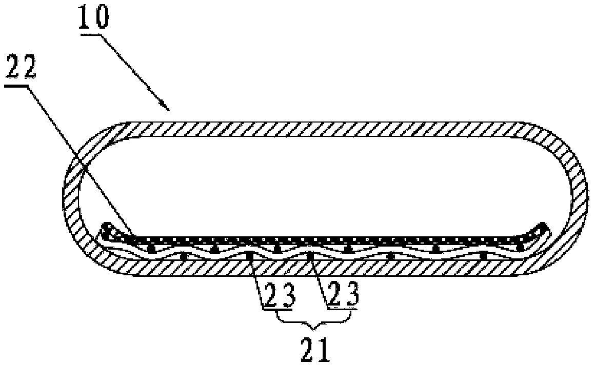
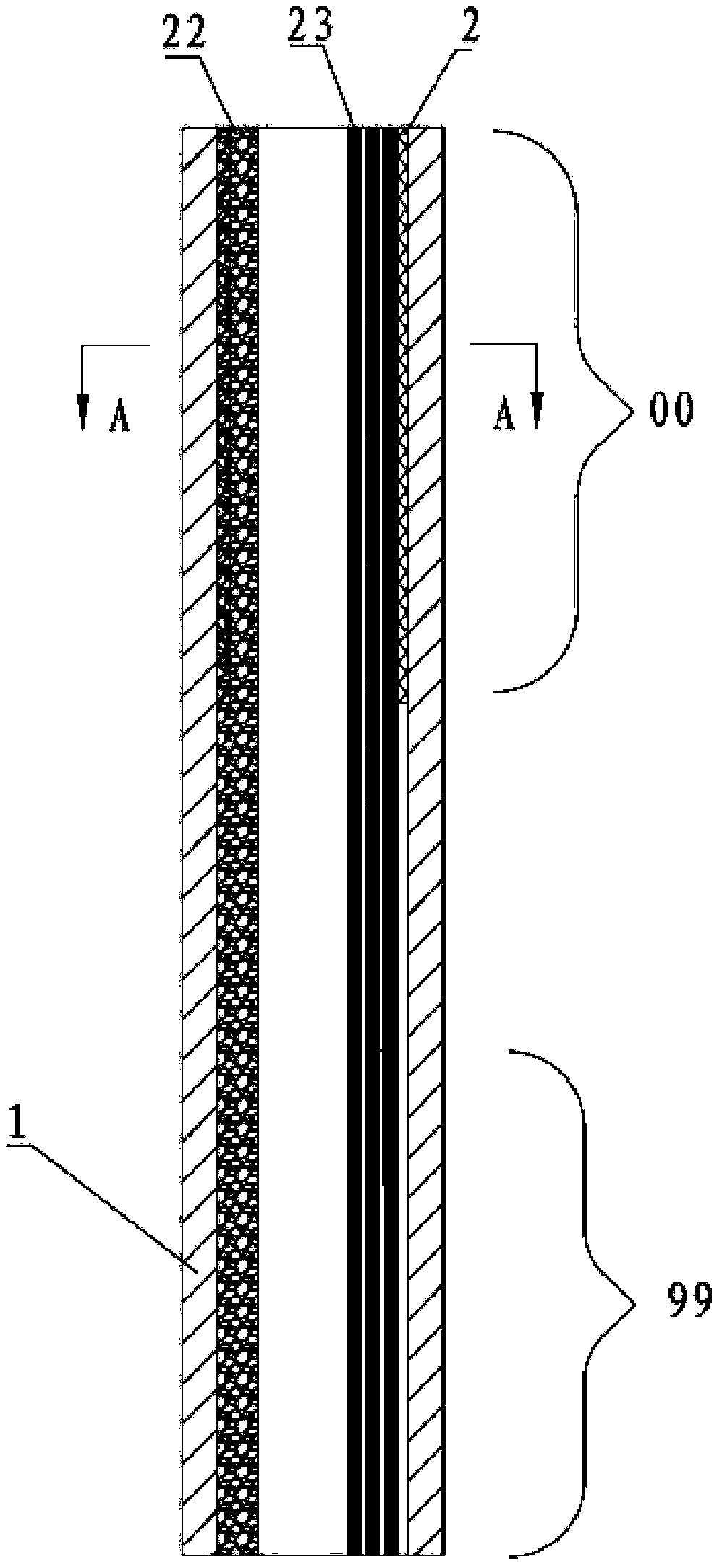
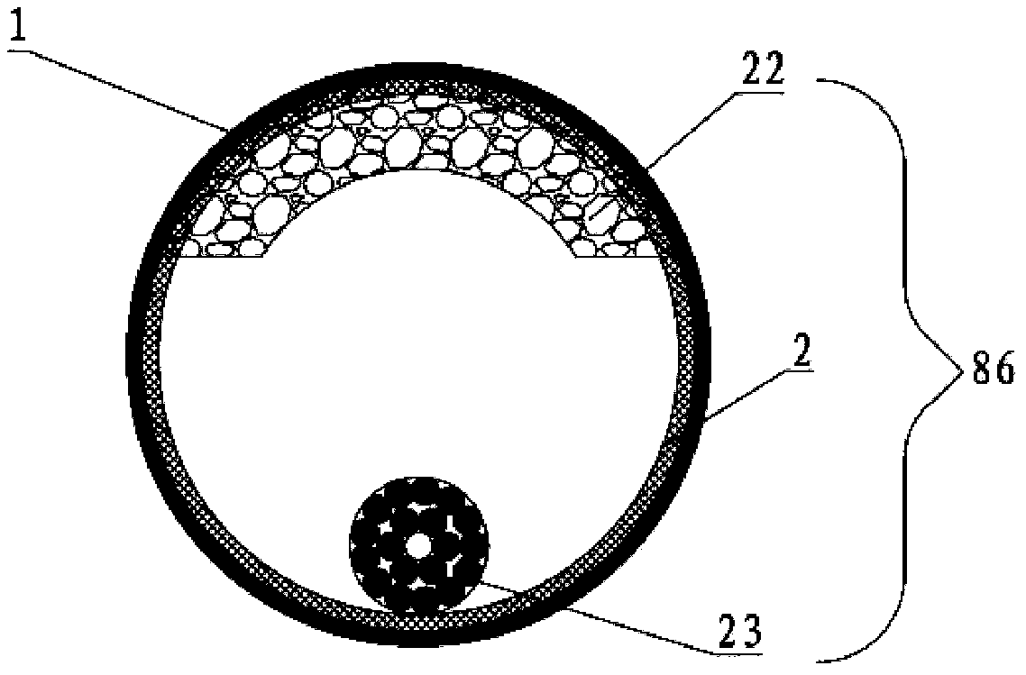
[0033] combine figure 2 with image 3 , the tube body of the heat pipe before being flattened is a circular copper tube, including a tube body 1 and an evaporation section 00 and a condensation section 99 located at both ends of the tube body 1, and a composite sintering section is arranged in the lumen of the tube body 1 capillary structure 86, the composite sintered capillary structure 86 includes a metal wire 23 and a metal mesh, the metal mesh 2 is arranged on the inner peripheral surface of the tube body 1 of the evaporation section, and the metal wire 23 is arranged along the axial direction of the tube body 1 One side of the inner peripheral surface is arranged in a circular shape. As a preferred method, the diameter of the metal wires in this embodiment is less than or equal to 0.6 copper wires. In order to play a bet...


PUM

PropertyMeasurementUnit
Diameteraaaaaaaaaa
Wire diameteraaaaaaaaaa
Thicknessaaaaaaaaaa

Abstract

The invention discloses a flat type heat pipe and a manufacturing method of the flat type heat pipe. The flat type heat pipe comprises a pipe body, an evaporation section and a condensation section, the evaporation section and the condensation section are arranged at the two ends of the pipe body respectively, a compound sintering capillary structure is arranged in a pipe chamber of the pipe body, the compound sintering capillary structure comprises metal wires and a metal mesh, the metal mesh is arranged on an inner circumferential face of the pipe body of the evaporation section, and the metal wires are arranged along one side face of the axial inner circumferential face of the pipe body in a circumference mode. The flat type heat pipe can effectively ensure the fact that steam flows back to the condensation section when the heat pipe is flattened to be quite thin, can effectively ensure reliability of production of the heat pipe, and further improves efficiency of heat conduction of the heat pipe.

Description

technical field [0001] The invention relates to the technical field of heat dissipation, in particular to a flat heat pipe and a manufacturing method thereof. Background technique [0002] As the product structure of the microcomputer industry (notebook computer, tablet computer) is moving towards lighter, thinner and smaller, the processor is developing in the direction of high speed and high power. However, in the process of continuous improvement of product performance, the problems caused by its heat generation are becoming more and more serious, and the heat generation of electronic components is increasing. In order to solve the aforementioned problems, many passive heat transfer elements have been proposed one after another, such as: heat pipe (Heat Pipe), Loop Heat Pipe (LHP), Flat Plate Heat Pipe, Vapor Chamber Heat Spreader and Heat Sink, etc. [0003] It has the same working principle. There is a capillary structure on the inner surface of a vacuum shell, and it ...

Claims


Application Information

Patent Timeline
IPC IPC(8): F28D15/04B23P15/26
CPCF28D15/0233F28D15/046
Inventor 朱胜利
Owner KUN SHAN DOTOP METAL TECH CO LTD
Why Eureka
Try Eureka