Revolving glass mold fixture device

A fixture device and glass mold technology, applied in the field of tooling and fixtures, can solve the problems of poor adaptability of glass molds, large material consumption, resource saving, difficulty in manufacturing and assembly, etc., to achieve maintenance and maintenance, simple overall structure, The effect of saving equipment investment

Active Publication Date: 2013-10-23
CHANGSHU JIANHUA MOLD TECH
View PDF25 Cites 5 Cited by
  • Summary
  • Abstract
  • Description
  • Claims
  • Application Information

AI Technical Summary

Problems solved by technology

However, this patent scheme has the following shortcomings: First, because this patent is used as a transitional mechanism between industrial robots and plasma spray welding machines, that is, it needs to be used with industrial robots because it cannot turn around itself, so it is widely used in my country. For large and medium-sized glass mold manufacturers, it is not only difficult to invest in industrial robots, but also has technical bottlenecks in use and maintenance; The adaptability of the size of the glass mold is relatively poor; third, the overall structure is still relatively complex, which poses certain difficulties in manufacturing and assembly, and consumes a lot of materials, which is not conducive to saving resources; fourth, although the patent can make the sprayed The welded glass mold exhibits the degree of freedom of rotation as needed, but because it is realized by the wrist movement of the robot, it does not provide the clamping of the half-mold of the glass mold with an ordinary device under the premise of getting rid of the control of the robot. Enlightenment of Institutions Being Free to Turn

Method used


Image

  • Revolving glass mold fixture device
  • Revolving glass mold fixture device

Examples


Embodiment Construction

[0022] In order to enable the examiners of the patent office, especially the public, to understand the technical essence and beneficial effects of the present invention more clearly, the applicant will describe in detail the following in the form of examples, but none of the descriptions to the examples is an explanation of the solutions of the present invention. Any equivalent transformation made according to the concept of the present invention which is merely formal but not substantive shall be regarded as the scope of the technical solution of the present invention.

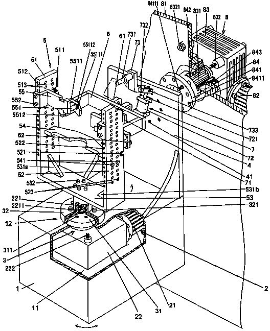
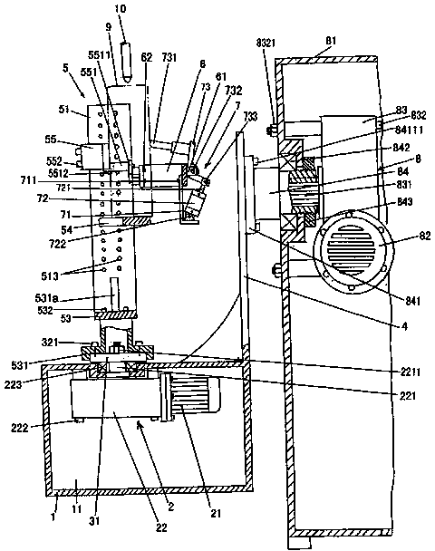
[0023] See figure 1 , a rectangular revolving seat 1 is given, and the revolving seat 1 constitutes or has a revolving seat cavity 11 . A mold clamping frame rotary drive mechanism 2 is given, the mold clamping frame rotary drive mechanism 2 includes a clamping frame driving motor 21 and a clamping frame driving reduction box 22, and the clamping frame driving motor 21 has the function of forward and reverse ...


PUM


Abstract

A revolving glass mold fixture device belongs to the technical field of fixtures, and comprises a revolving bed, a mold clamping frame revolving drive mechanism, a mold clamping frame transition connection mechanism, a wallboard, a mold clamping frame, a mold limiting frame and a mold back limiting mechanism, wherein the revolving bed is provided with a revolving bed chamber; the mold clamping frame revolving drive mechanism is arranged in the revolving bed chamber; the mold clamping frame transition connection mechanism is connected with the mold clamping frame revolving drive mechanism; the wallboard is fixed with the edge part at the upper part of the rear end of the revolving bed, and is perpendicular to the revolving bed; the mold clamping frame is connected with the mold clamping frame transition connection mechanism above a part corresponding to the revolving bed; the mold limiting frame is arranged on the mold clamping frame; the mold back limiting mechanism is arranged on the mold limiting frame. A half glass mold clamped on the mold clamping frame has favorable revolving freedom in cooperating with a welding gun of a plasma spray welding machine to act, without depending on an industrial robot. The equipment investment is saved, the clamping reliability is ensured, the structure is simple, the operation is convenient, the maintenance is facilitated, and the revolving bed can be enabled to revolve together with the mold clamping frame.

Description

technical field [0001] The invention belongs to the technical field of fixtures, and in particular relates to a rotatable glass mold fixture device. Background technique [0002] In the molding process of glass products, for glass molds with two or more openings, the mold cavity is directly in frequent contact with the molten glass melt, and is subjected to chemical erosion, abrasion and alternating stress of cold and heat of the glass (cold and hot). Alternate thermal stress), and service at a temperature of about 500-800°C, the surface of the cavity, the seam surface and even the end faces at both ends are easily oxidized, and there is an unavoidable impact between the mold parts, which will cause and Not limited to the following damage situations: fatigue damage, mechanical impact damage, oxidation corrosion damage and wear damage. [0003] In order to improve the oxidation resistance, corrosion resistance, thermal fatigue resistance and wear resistance of the glass mold...

Claims


Application Information

Patent Timeline
IPC IPC(8): B23K37/04B23K37/047B23K10/02
Inventor 朱伟国方朝辉苏秋君晏庆宝韩志强苏彬彬
Owner CHANGSHU JIANHUA MOLD TECH
Why Eureka
Try Eureka