
A winding evaporation vacuum coating machine

A vacuum coating machine, evaporative technology, applied in the direction of vacuum evaporation coating, sputtering coating, ion implantation coating, etc., can solve the problems of laborious, reduced production efficiency, poor adhesion, etc., to improve the anti-oxidation ability, Improve production efficiency, strong binding effect

Inactive Publication Date: 2016-07-06
郑州华翔电子信息技术有限公司
View PDF11 Cites 0 Cited by
  • Summary
  • Abstract
  • Description
  • Claims
  • Application Information

AI Technical Summary

Problems solved by technology

[0002] At present, zinc-aluminum composite evaporation technology is used in China, but the zinc-aluminum composite film after plating is easy to oxidize in the atmosphere, and has high requirements for storage. It needs vacuum packaging and keeps the ambient temperature and humidity constant.
The zinc-aluminum composite film has poorer adhesion than the aluminum film, and requires two sets of equipment to vaporize the aluminum film and vaporize the zinc film respectively. When replacing the two sets of equipment, it will be time-consuming, laborious, and reduce the production efficiency.
The aluminum has a strong bond with the base film, and a dense layer of aluminum oxide film is formed on the surface of the aluminum layer in the air. This layer of aluminum oxide film can protect the inner layer of aluminum from further oxidation, but the ordinary evaporated aluminum film The equipment can only evaporate one layer of aluminum film, and the thickness of the aluminum film on the edge and the middle part is the same, and its pressure resistance is low and the loss is high

Method used


Image

  • A winding evaporation vacuum coating machine

Examples


Embodiment Construction

[0015] The present invention will be described in further detail below in conjunction with the accompanying drawings.

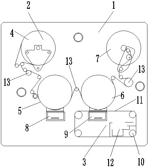
[0016] like figure 1 As shown, a roll-to-roll evaporation vacuum coating machine includes a vacuum chamber 1 and a roll-to-roll evaporation system 2 , a shielding system 3 and a motor arranged in the vacuum chamber 1 .

[0017] The winding evaporation system 2 includes a hair reel 4, a No. 1 evaporation drum 5, a No. 2 evaporation drum 6, a winding shaft 7, a No. 1 aluminum evaporator 8 and a No. 2 aluminum evaporator 9; It is arranged in the upper left corner of the vacuum chamber 1, the winding shaft 7 is arranged in the upper right corner of the vacuum chamber 1, and the No. Below the reel 4 and the winding shaft 7; the No. 1 aluminum evaporator 8 is directly below the No. 1 evaporation drum 5, and the No. 2 aluminum evaporator 9 is directly below the No. 2 evaporation drum 6; the shielding system 3 is located in a vacuum chamber 1 lower right corner, in...


PUM


Abstract

The invention belongs to the technical field of vacuum coating, and especially relates to a winding evaporation type vacuum coating machine. The vacuum coating machine comprises a vacuum chamber, and a rolling evaporation system, a shielding system and a motor which are arranged in the vacuum chamber. An unwinding shaft is arranged at the top left corner of the vacuum chamber, a winding shaft is arranged at the top right angle of the vacuum chamber, a first evaporation coating drum and a second evaporation coating drum are arranged between the unwinding shaft and the winding shaft side by side, and are positioned below the unwinding shaft and the winding shaft. A first aluminum evaporator is positioned just below the first evaporation coating drum, and a second aluminum evaporator is positioned just below the second evaporation coating drum; and the shielding system is positioned at the bottom right corner of the vacuum chamber, the shielding steel band of the shielding system traverses between the second aluminum evaporator and the second evaporation coating drum, and the aluminum recovery device of the shielding system is arranged at the bottom right of the shielding system. Each of the winding evaporation system and the shielding system is connected with the motor. The vacuum coating machine has the advantages of one-time completion of the coating and edge thickening, long storage time, stable and unchanged performances, simple operation and production efficiency increase.

Description

technical field [0001] The invention belongs to the technical field of vacuum coating, in particular to a winding evaporation vacuum coating machine. Background technique [0002] At present, zinc-aluminum composite evaporation technology is used in China, but the zinc-aluminum composite film after plating is easy to oxidize in the atmosphere, and has high requirements for storage. It needs vacuum packaging and keeps the ambient temperature and humidity constant. The zinc-aluminum composite film has poorer adhesion than the aluminum film, and requires two sets of equipment to evaporate the aluminum film and the zinc film respectively. When replacing the two sets of equipment, it will be time-consuming, laborious, and reduce the production efficiency. The aluminum has a strong bond with the base film, and a dense layer of aluminum oxide film is formed on the surface of the aluminum layer in the air. This layer of aluminum oxide film can protect the inner layer of aluminum fro...

Claims


Application Information

Patent Timeline
Patent Type & Authority Patents(China)
IPC IPC(8): C23C14/56C23C14/24
Inventor 林正亮
Owner 郑州华翔电子信息技术有限公司
Learn More