Compressor, air conditioning system with same and heat-pump water heater system

A compressor, high-pressure compression technology, applied in the direction of compressors, machines/engines, machine operation modes, etc., can solve problems such as affecting compressor fullness, large airflow pulsation, reducing compressor efficiency and compressor energy efficiency.

Active Publication Date: 2013-10-23
ZHUHAI GREE REFRIGERATION TECH CENT OF ENERGY SAVING & ENVIRONMENTAL PROTECTION
View PDF7 Cites 22 Cited by
  • Summary
  • Abstract
  • Description
  • Claims
  • Application Information

AI Technical Summary

Problems solved by technology

[0002] In the prior art, after the two-stage enthalpy-increasing compressor with dual rotors performs gas replenishment and enthalpy increase, the pressure and flow rate of the refrigerant in different stages in the medium-pressure gas flow channel are different, while the cross-sectional area of ​​the medium-pressure gas flow channel is the same Yes, this leads to a large airflow pulsation between the discharge of the low-pressure compression component of the first stage and the suction of the high-pressure compression component of the second stage, which affects the suction of the compressor and the fullness of the exhaust, thereby reducing the compressor efficiency and compressor energy efficiency, increasing energy consumption

Method used


Image

  • Compressor, air conditioning system with same and heat-pump water heater system
  • Compressor, air conditioning system with same and heat-pump water heater system
  • Compressor, air conditioning system with same and heat-pump water heater system

Examples


no. 1 example

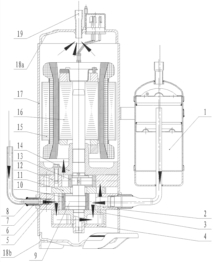
[0047] Figure 1 to Figure 15 The compressor of the first embodiment of the present invention is shown, and the compressor is a two-stage enthalpy-increasing compressor with the medium-pressure chamber at the lower part of the low-pressure chamber.

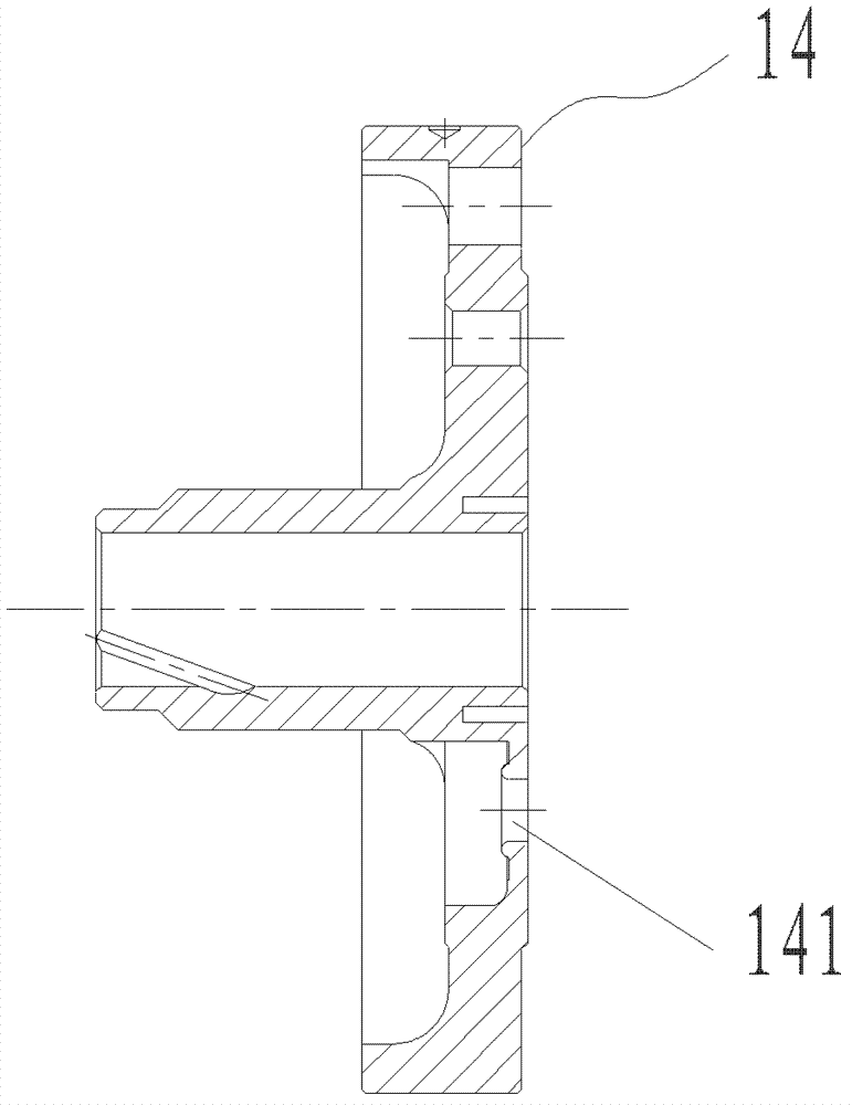
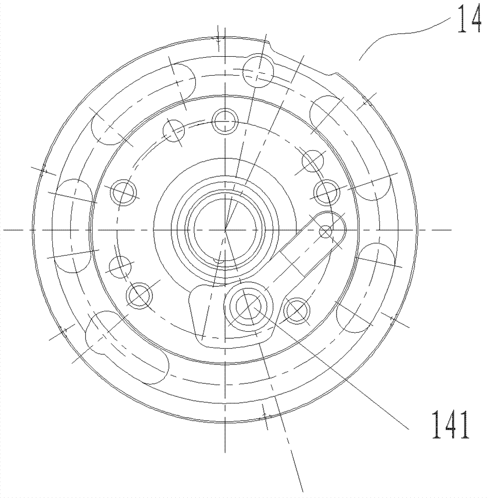
[0048] The compressor of the first embodiment mainly includes a shell assembly, a motor, a low-pressure compression assembly, an enthalpy-increasing assembly, a lower flange 3, a high-pressure compression assembly, a pump body partition 11, an upper flange 14, a liquid separator 1, and the like.

[0049]The case assembly includes an upper case 18a, a middle case 17 and a lower case 18b. The motor is arranged inside the shell assembly and mainly consists of a stator 15 and a rotor 16 . The low-pressure compression assembly mainly includes a low-pressure cylinder 2 and a low-pressure roller 10 arranged in the low-pressure cylinder 2 . A concave cavity is arranged below the lower flange 3, and the lower cover plate 4 is set on the ...

no. 2 example

[0068] Such as Figure 24 As shown, the compressor of the second embodiment is a two-stage enthalpy-increasing compressor with a medium-pressure chamber between the low-pressure compression assembly and the high-pressure compression assembly, which mainly includes a liquid separator 201, a low-pressure cylinder 202, an intermediate cylinder 203, and an enthalpy-increasing compressor. Pipe 204, pump body partition 205, high pressure cylinder 206, upper flange 207 and lower flange 208 and so on. In the compressor of the second embodiment, since the medium-pressure chamber is arranged on the upper part of the low-pressure chamber, the medium-pressure refrigerant of the whole compressor directly flows upward to the high-pressure compression assembly.

[0069] In the second embodiment, the liquid distributor 201 is connected with the low-pressure cylinder 202 through the suction pipe, the low-pressure cylinder 202 is fixed on the lower flange 208 by screws, the middle cylinder 203 ...

no. 3 example

[0076] Such as Figure 25 As shown, the compressor of the third embodiment forms a two-stage enthalpy-increasing compressor with an external structure of a medium-pressure cavity by adding an external airtight intermediate box. The compressor of the third embodiment mainly includes a motor, a low-pressure compression assembly, an intermediate box 304, a high-pressure compression assembly, a shell assembly, a liquid separator 301 and the like.

[0077] The liquid distributor 301 is connected with the low-pressure cylinder 302 through the suction pipe, the low-pressure cylinder 302 is fixed on the lower flange 303 by screws, the middle box 304 is fixed on the shell assembly 309 by welding, and the middle box 304 passes through the first exhaust The pipe communicates with the exhaust port of the low-pressure cylinder on the low-pressure cylinder 302, and communicates with the suction port of the high-pressure cylinder on the high-pressure cylinder 307 through the second exhaust p...


PUM


Abstract

A compressor, an air conditioner system comprising the compressor and a heat pump water heater system. The compressor comprises: a low-pressure compression component, a medium-pressure chamber, a low-pressure chamber air discharge passageway, an enthalpy-increasing component, a high-pressure compression component, a medium-pressure air passageway and a high-pressure chamber air discharge passageway. The medium-pressure air passageway comprises a side passageway section of the low-pressure chamber air discharge passageway and a side passageway section of a high-pressure chamber air suction passageway, and a ratio between a minimum cross section area of the side passageway section of the low-pressure chamber air discharge passageway and a minimum cross section area of the side passageway section of the high-pressure chamber air suction passageway is from 1.4 to 4. In the compressor, the pressure impulse and the flow speed impulse of the refrigerant are relatively small, the first-stage air discharge plumpness and the second-stage air discharge plumpness can be improved, and the air supply quantity can be improved; therefore, the working efficiency and the energy efficiency of the compressor are enhanced, and the energy consumption is reduced.

Description

technical field [0001] The invention relates to the fields of air conditioners and heat pumps, and more specifically, to a compressor, an air conditioner system with the compressor, and a heat pump water heater system. Background technique [0002] In the prior art, after the two-stage enthalpy-increasing compressor with dual rotors performs gas replenishment and enthalpy increase, the pressure and flow rate of the refrigerant in different stages in the medium-pressure gas flow channel are different, while the cross-sectional area of ​​the medium-pressure gas flow channel is the same Yes, this leads to a large airflow pulsation between the discharge of the low-pressure compression component of the first stage and the suction of the high-pressure compression component of the second stage, which affects the suction of the compressor and the fullness of the exhaust, thereby reducing the compressor Efficiency and compressor energy efficiency, which increases energy consumption. ...

Claims


Application Information

Patent Timeline
Patent Type & Authority Applications(China)
IPC IPC(8): F04C23/00F04C29/00
CPCF04C29/00F04C23/00F04C23/001F04C23/008F04C28/02F04C29/0035F04C18/356F01C21/10F04C29/042F04B1/12F04B25/04F25B29/003F25B31/00
Inventor 魏会军李万涛
Owner ZHUHAI GREE REFRIGERATION TECH CENT OF ENERGY SAVING & ENVIRONMENTAL PROTECTION
Why Eureka
Try Eureka