Light guide plate production method

A manufacturing method and technology of light guide plates, applied in the direction of light guides, optics, optical components, etc., can solve problems such as slow processing speed, incapable of mass production, and difficult adjustment of UV exposure angle, so as to prevent surface chromatic aberration, easy adjustment, and exposure The effect of easy control of the amount

Inactive Publication Date: 2013-10-23
北京众普寰宇新光源科技有限公司
View PDF2 Cites 3 Cited by
  • Summary
  • Abstract
  • Description
  • Claims
  • Application Information

AI Technical Summary

Problems solved by technology

At present, the manufacturing methods of the scattering layer mainly include printing and laser processing. The printing method is as follows: Figure 1a As shown, the fluorescent powder and other scattering materials are printed on the bottom of the light guide plate, and the scattering pattern is formed by the printing pattern composed of phosphor powder. The advantage of this method is that it can be mass-produced. The disadvantage is that the brightness of the light emitted by the light guide plate is low. method such as Figure 1b As shown, multiple depressions are formed on the bottom of the light guide plate, and the depressions form a scattering pattern. The advantage of this method is that the brightness of the light emitted by the light guide plate is high. The disadvantage is that laser processing cannot be mass-produced, and the processing speed is slow and the equipment is expensive. High processing cost
Over the past few years, a method of manufacturing light guide plates by imprinting has been developed. The specific steps are as follows: figure 2 As shown, in this method, the UV curable resin is coated on the light guide plate body, and then the UV curable resin is embossed with a mold, and the UV curable resin is exposed to ultraviolet light (UV), so that the resin is cured to form a diffuser. pattern, and then release the mold. This manufacturing method can combine the advantages of printing and laser processing. The brightness of the light emitted by the light guide plate is high, which can be mass-produced, and the processing speed is fast and the processing cost is low. However, due to UV exposure before the release, Therefore, the UV exposure process is limited by the mold and is not flexible enough. For example, the angle of UV exposure is not easy to adjust, the amount of UV exposure is not easy to control, and it is easy to cause problems such as surface color difference.

Method used


Image

  • Light guide plate production method
  • Light guide plate production method
  • Light guide plate production method

Examples


Embodiment 1

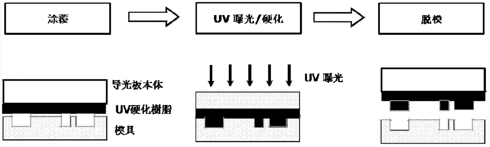
[0027] This embodiment provides a method for manufacturing a light guide plate, such as image 3 shown, including:

[0028] On the light guide plate body that is made by PMMA, coat UV hardening resin, the composition of this UV hardening resin comprises the MMA that mass percentage is 15% ( Propylene methyl ester), 20% trimethylolpropane triacrylate, 2% photoinitiator (Photoinitiator), 63% solvent;

[0029] Embossing the UV curable resin with a mold;

[0030] Release from the mold to form a scattering pattern that complements the shape of the mold;

[0031] The UV curable resin is exposed to ultraviolet light to harden the UV curable resin to form a final scattering pattern on the light guide plate body.

[0032] In the present invention, the order of exposure and demoulding is changed, and UV exposure is performed after demoulding. Compared with the prior art, the position of the exposure light source is not limited, and the angle of exposure is easier to adjust. The exp...

Embodiment 2

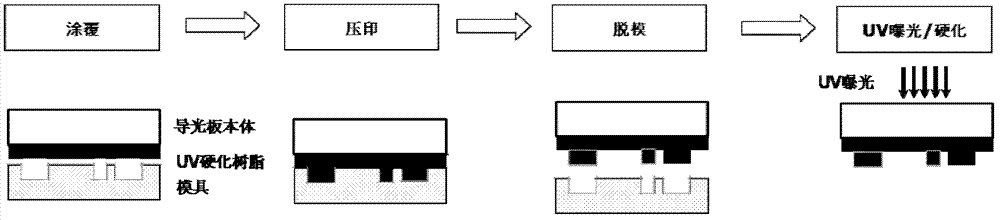
[0038] This embodiment provides a Figure 4 The manufacturing method of the shown light guide plate includes:

[0039] coating a UV curable resin on the first side of the light guide plate body;

[0040] embossing the UV curable resin on the first side of the light guide plate body with a mold having a raised pattern to form a scattering pattern;

[0041] demoulding;

[0042] exposing the UV curable resin on the first side of the light guide plate body under ultraviolet light to harden the UV curable resin, thereby forming a concave pattern complementary to the shape of the mold in the UV curable resin on the first side of the light guide plate body, As the scattering layer of the light guide plate;

[0043] coating a UV curable resin on a second side of the light guide plate body opposite to the first side;

[0044] embossing the UV curable resin on the second side of the light guide plate body with a mold having a concave pattern to form a diffusion pattern;

[0045] de...


PUM

PropertyMeasurementUnit
thicknessaaaaaaaaaa

Abstract

The invention provides a light guide plate production method which comprises the following steps: 1) UV (ultra violet) hardened resin is coated on a light guide plate body; 2) the UV hardened resin is imprinted by a die; 3) demoulding is carried out to form a pattern complementary with a shape of the die in the hardened resin; 4) the UV hardened resin is exposed in ultraviolet light so as to harden the UV hardened resin.

Description

technical field [0001] The present invention relates to a method for manufacturing a light guide panel (LGP), in particular to a method for manufacturing a light guide panel by using an imprint method. Background technique [0002] In the liquid crystal display, since the liquid crystal panel does not have the function of emitting light, a back light unit (BLU) is placed under the liquid crystal panel to provide a source of light to achieve the display function. In the backlight unit, cold cathode fluorescent lamp (cold cathode fluorescent lamp, CCFL), LED (light-emitting diode), etc. are usually used as the light source, and LED has gradually become the mainstream light source because of its low power consumption and good environmental protection characteristics. Moreover, the LED light source can also make the liquid crystal display thinner and lighter. Existing backlight units usually also include a light guide plate and a plurality of optical films, such as diffusion sh...

Claims


Application Information

Patent Timeline
Patent Type & Authority Applications(China)
IPC IPC(8): G02B6/00F21V8/00
Inventor 具东孝尹仁洙
Owner 北京众普寰宇新光源科技有限公司
Why Eureka
Try Eureka