High-strength micro optical fiber cable and manufacturing method thereof

A high-strength, optical cable technology, applied in the direction of fiber mechanical structure, etc., can solve the problems of reducing initial investment, low utilization rate, and high investment cost

Inactive Publication Date: 2013-10-23
SHENZHEN SDG INFORMATION CO LTD
View PDF4 Cites 5 Cited by
  • Summary
  • Abstract
  • Description
  • Claims
  • Application Information

AI Technical Summary

Problems solved by technology

For many years, our understanding of loose-tube optical cables has basically stayed on the loose-tube structure made of polymer engineering plastics (such as PBT), although power OPGW and OPPC optical cables and submarine optical cables use seamless stainless steel tubes (Stainless Steel Tube , hereinafter referred to as SST) structure, but for a long time, due to stainless steel tube welding process, raw material supply, production equipment, cost, production efficiency and other issues, people have restricted the development of people's application of seamless stainless steel tube optical fiber technology to conventional optical cables.
At present, the micro-optical cables on the market use stainless steel tubes as the strengthening layer. The optical fibers and optical fibers are located in the stainless steel tubes. , but its strength, especially the tensile strength, still has room for improvement
[0003]It is a new product developed to solve the current problems of high investment cost and low utilization rate that restrict the healthy development of optical cable network. It can not only reduce the initial investment, but also With the growth of customer demand, simultaneous investment, reuse of existing pipeline resources, enlarged capacity, and value-added services

Method used


Image

  • High-strength micro optical fiber cable and manufacturing method thereof

Examples


Embodiment Construction

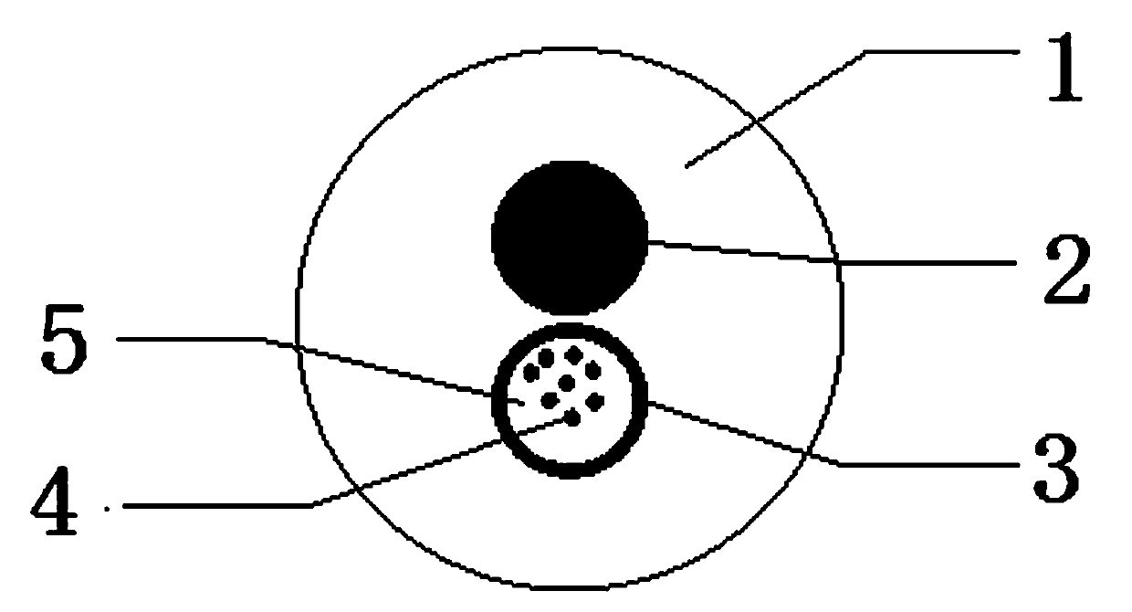
[0019] The present invention will be further described below in conjunction with accompanying drawing:

[0020] Refer to attached figure 1 , a high-strength micro-optical cable, including a stainless steel tube 3 light unit for protecting the optical fiber 4, a strength member 2 (phosphating steel wire or glass fiber reinforced resin) to strengthen the optical cable, and a sheath 1 for protecting the optical cable The optical unit of the stainless steel tube 3 and the reinforcing member 2 cover the sheath 1, and the optical unit of the stainless steel tube 3 is provided with several optical fibers 4 for transmitting optical signals.

[0021] Preferably, the stainless steel tube 3 optical unit includes a steel tube coated on the outer layer, a number of optical fibers 4 for transmitting optical signals and an optical fiber ointment 5 for fixing the position of the optical fiber 4, and the number of optical fibers 4 is 4 ~24 pieces, the outer diameter of the stainless st...


PUM

PropertyMeasurementUnit
thicknessaaaaaaaaaa
diameteraaaaaaaaaa

Abstract

The invention discloses a high-strength micro optical fiber cable and a manufacturing method thereof, and relates to the field of micro optical fiber cables of a special type. The high-strength micro optical fiber cable comprises a stainless steel tube light unit used for protecting an optical fiber, a strengthening piece for strengthening the strength of an optical fiber cable, and a sheath for protecting the optical fiber cable; the sheath covers outside the stainless steel tube light unit and the strengthening piece; and a plurality of optical fibers used for transmitting light signals are built in the stainless steel tube light unit. The optical fiber of the type consists of the stainless steel tube light unit, the high-strength strengthening piece and the sheath; the process of the optical fiber cable is easy and convenient to operate, and easy to control; the optical fiber cable is simple in structure and small in outside diameter, saves pipeline resources, and is applied to various places of pipelines, indoors, short-distance burial and overhead and the like.

Description

technical field [0001] The invention relates to the field of communication optical cables, in particular to a novel high-strength optical cable with excellent weather resistance. Background technique [0002] With the advent of the information age, the amount of information transmission has increased explosively. As an effective means of large-capacity and long-distance transmission, fiber optic cables have been widely used. Micro-optical cables appear according to the needs of users and market development. For many years, our understanding of loose-tube optical cables has basically stayed on the loose-tube structure made of polymer engineering plastics (such as PBT), although power OPGW and OPPC optical cables and submarine optical cables use seamless stainless steel tubes (Stainless Steel Tube , hereinafter referred to as SST) structure, but for a long time, due to stainless steel tube welding process, raw material supply, production equipment, cost, production efficiency...

Claims


Application Information

Patent Timeline
Patent Type & Authority Applications(China)
IPC IPC(8): G02B6/44
Inventor 苏海芳邓伟锋何文栋韦文波张玥雷达
Owner SHENZHEN SDG INFORMATION CO LTD
Why Eureka
Try Eureka