Cleaning method and cleaning system of reaction cavity

A cleaning system and reaction chamber technology, applied in the field of reaction chamber cleaning and reaction chamber cleaning systems, can solve problems such as uneven cleaning, inconsistent path length, inconsistent cleaning speed, etc., to shorten cleaning time, reduce production costs, and save Effect of purge gas

Active Publication Date: 2013-10-30
理想万里晖真空装备(泰兴)有限公司
View PDF3 Cites 11 Cited by
  • Summary
  • Abstract
  • Description
  • Claims
  • Application Information

AI Technical Summary

Problems solved by technology

However, after the cleaning gas is dissociated by the RPS, it is transported into one or more reaction chambers to be cleaned by a common path, which is prone to the following four problems: 1) Because the flow resistance is not easy to control, the gas flow distribution to each chamber is inconsistent, and it is easy to The cleaning speed between the chambers is inconsistent, and the slowest chamber will determine the final cleaning time, resulting in a longer cleaning time; 2) The transmission path is long and the length of the path to each chamber is inconsistent, and the composite loss rate of active particles Not only is it high, but the recombination loss rate between each chamber is also inconsistent, which eventually leads to uneven cleaning; 3) After the cleaning gas is dissociated by the RPS, it diffuses and migrates from the outer edge of the reaction chamber to the inside of the reaction chamber, resulting in a slower cleaning speed at the edge of the chamber. Greater than the cleaning speed inside the chamber, the cleaning is uneven; 4) RPS uses much more cleaning gas than the in-situ plasma cleaning method, and the cost of cleaning gas is higher, which increases the production cost of the product

Method used


Image

  • Cleaning method and cleaning system of reaction cavity
  • Cleaning method and cleaning system of reaction cavity
  • Cleaning method and cleaning system of reaction cavity

Examples


Embodiment Construction

[0069] In order to make the above objects, features and advantages of the present invention more comprehensible, specific implementations of the present invention will be described in detail below in conjunction with the accompanying drawings.

[0070] In the following description, many specific details are set forth in order to fully understand the present invention, but the present invention can also be implemented in other ways than those described here, so the present invention is not limited by the specific embodiments disclosed below.

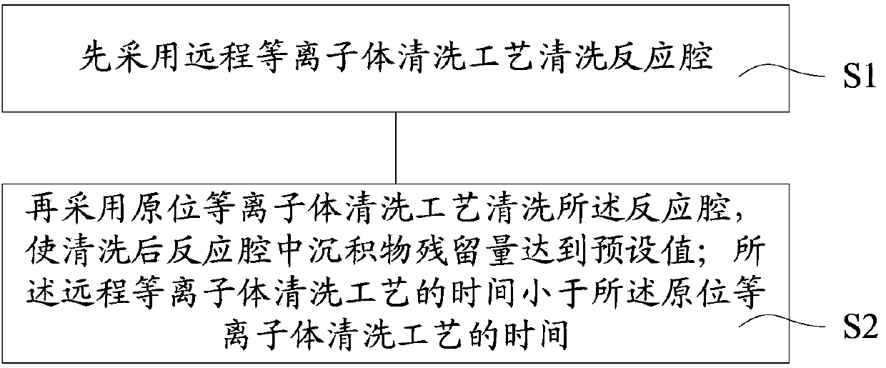
[0071] As mentioned in the background technology section, when only RPS is used to clean the reaction chamber in the prior art, there are disadvantages such as long cleaning time, waste of cleaning gas, and uneven cleaning. When only the in-situ plasma cleaning process is used to clean the reaction chamber, It has the disadvantages of uneven cleaning, low cleaning efficiency and long cleaning time.

[0072] In view of the above defects, t...


PUM

PropertyMeasurementUnit
thicknessaaaaaaaaaa
thicknessaaaaaaaaaa

Abstract

The invention discloses a cleaning method and a cleaning system of a reaction cavity. The cleaning method of the reaction cavity comprises the following steps of: firstly cleaning the reaction cavity by adopting a long-distance plasma body cleaning process, cleaning the reaction cavity by adopting a normal position plasma body cleaning process, enabling the sediment residual quantity in the reaction cavity after cleaning to achieve a preset value, wherein the time of the long-distance plasma body cleaning process is less than that of the normal position plasma body cleaning process. The cleaning method and the cleaning system provided by the invention have the advantages that the cleaning time is reduced, the cleaning uniformity is improved, and the use amount of the cleaning gas is also reduced.

Description

technical field [0001] The invention relates to the technical field of semiconductors, in particular to a method for cleaning a reaction chamber and a cleaning system for the reaction chamber. Background technique [0002] In the semiconductor or solar energy production process, it is necessary to regularly clean the inner surface of the reaction chamber, the surface of the gas distribution plate, the surface of the cover, the surface of the fixture, etc., to avoid the resulting pollution affecting the quality of the product. [0003] Existing cleaning processes include sand blasting, wet cleaning, in situ plasma (in situ plasma) cleaning, remote plasma source (RPS) cleaning, and the like. [0004] Sand blasting uses compressed air as the power to form an adjusted jet beam to spray the spray material onto the surface of the workpiece to be processed at high speed. Due to the impact and cutting effect of the abrasive on the surface, the surface of the workpiece can be cleaned...

Claims


Application Information

Patent Timeline
Patent Type & Authority Applications(China)
IPC IPC(8): C23C16/44
Inventor 陈金元马哲国王慧慧吴科俊
Owner 理想万里晖真空装备(泰兴)有限公司
Why Eureka
Try Eureka