
Method and drainage device for preventing rainwater from entering stockyard

A technology for drainage devices and storage yards, applied in water supply devices, protection devices, waterway systems, etc., can solve the problems of incomplete discharge of polluted wastewater, poor connection between clay and drainage pipes, and heavy sewage treatment workload, and achieve the initial reduction of Investment cost, easy management, and the effect of reducing high costs

Active Publication Date: 2016-02-10
GUIYANG AL-MG DESIGN & RES INST
View PDF6 Cites 0 Cited by
  • Summary
  • Abstract
  • Description
  • Claims
  • Application Information

AI Technical Summary

Problems solved by technology

The volume of the collection tank of this discharge method needs to be larger, the workload of sewage treatment is also large, and the treatment cost is high
In addition, the polluted waste water inside the waste residue cannot be completely discharged, and there is a potential danger.
At present, there is also a waste residue discharge method. In the process of stacking waste residue in the yard, each layer is piled up with clay with poor water permeability, so as to reduce the excessive amount of polluted water due to the infiltration of rainwater. Filling a layer of clay with a layer of waste slag requires a large amount of clay and high operating costs; as the amount of clay increases, the corresponding slag storage capacity decreases, which affects the design storage capacity; the connection between the clay and the drainage pipe is not easy to handle, and rainwater is easy to leak into the electrolytic slag and be polluted

Method used


Image

  • Method and drainage device for preventing rainwater from entering stockyard
  • Method and drainage device for preventing rainwater from entering stockyard
  • Method and drainage device for preventing rainwater from entering stockyard

Examples


Embodiment Construction

[0028] The present invention will be further described in detail below in conjunction with the accompanying drawings and embodiments, but not as any limitation to the present invention.

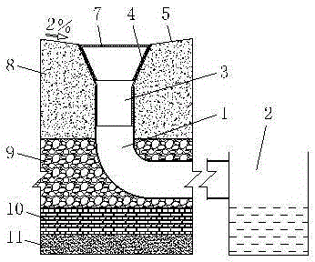
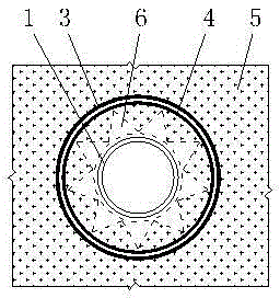
[0029] Methods to prevent rainwater from entering the yard, such as figure 1 As shown, the entire stockyard is divided into two or more stockpiling areas according to the amount of discharge; the next stockpiling area is activated after the first stockpiling area is filled; Leak detection layer 11, anti-seepage layer 10 and drainage layer 9, and then carry out waste slag discharge in stages on the drainage layer; after each discharge, lay geomembrane 5 on the surface of waste slag 8 to prevent rainwater from infiltrating waste slag 8; There are drain holes 6 (see figure 2 ), the drainage hole is connected with the drainage device, and the rainwater is discharged to the sump 2 outside the stockyard through the drainage device. According to the amount of discharge, the entire stockyard is di...


PUM


Abstract

The invention discloses a method and a drainage device for preventing rainwater from entering a storage yard. The method is to divide the entire stockyard into two or more stockpiling areas according to the amount of discharge; when the first stockpiling area is full, the next stockpiling area is opened; Leakage layer, anti-seepage layer and drainage layer, and then the waste residue is discharged in stages on the drainage layer; after each discharge, a geomembrane is laid on the surface of the waste residue to prevent rainwater from penetrating into the waste residue; there are drainage holes on the geomembrane, and the drainage holes and The drainage device is connected, and the rainwater is discharged to the sump outside the yard through the drainage device. this invention The unique discharge method can prevent rainwater from infiltrating waste residue, eliminate potential dangers, prevent excessive harmful sewage, greatly reduce the volume of the sump, reduce the workload of sewage treatment, and reduce the high cost of sewage treatment. Improve the utilization rate of the storage capacity of the storage yard, which can reduce the high operating cost; the present invention The advanced drainage device is economical, practical and easy to operate.

Description

technical field [0001] The invention relates to a method and a drainage device for preventing rainwater from entering a stockyard, and belongs to the technical field of environmental protection of the electrolytic waste slag stockyard. Background technique [0002] The waste slag produced by the overhaul of the electrolytic cell is hazardous solid waste. The electrolytic cell is overhauled at regular intervals. After each overhaul, a small part is recycled, and most of it is discharged into the waste slag yard. The main component of the leachate mixed with rainwater and waste residue is high-concentration inorganic fluoride, which cannot be discharged directly, and it is easy to introduce some serious environmental pollution and health hazards. [0003] At present, most of the storage methods and drainage conditions of domestic electrolytic slag yards are to directly discharge the waste slag generated by the overhaul of the electrolytic cell to the yard. The waste slag accu...

Claims


Application Information

Patent Timeline
Patent Type & Authority Patents(China)
IPC IPC(8): E03F1/00E02D31/00
Inventor 杨小全王胜安胡禹志
Owner GUIYANG AL-MG DESIGN & RES INST
Learn More