Current collector structure of positive electrode of lithium ion battery and battery including structure

A technology of lithium ion battery and positive current collector, applied in the field of lithium ion battery, can solve problems such as corrosion, and achieve the effect of avoiding corrosion and high strength

Inactive Publication Date: 2013-11-06
DONGGUAN AMPEREX TECH
View PDF7 Cites 10 Cited by
  • Summary
  • Abstract
  • Description
  • Claims
  • Application Information

AI Technical Summary

Problems solved by technology

[0004] The purpose of the present invention is to: address the deficiencies of the prior art, and provide a lithium-ion battery positive current collector structure, the positive current collector structure reduces the thickness of the positive current collector and improves the energy density of the battery, greatly improving the tensile strength of the current collector , and avoid the corrosion of the positive electrode to the main body material of the aluminum alloy layer, and at the same time, it is not easy to cause wrinkles and broken bands

Method used


Image

  • Current collector structure of positive electrode of lithium ion battery and battery including structure

Examples


Embodiment 1

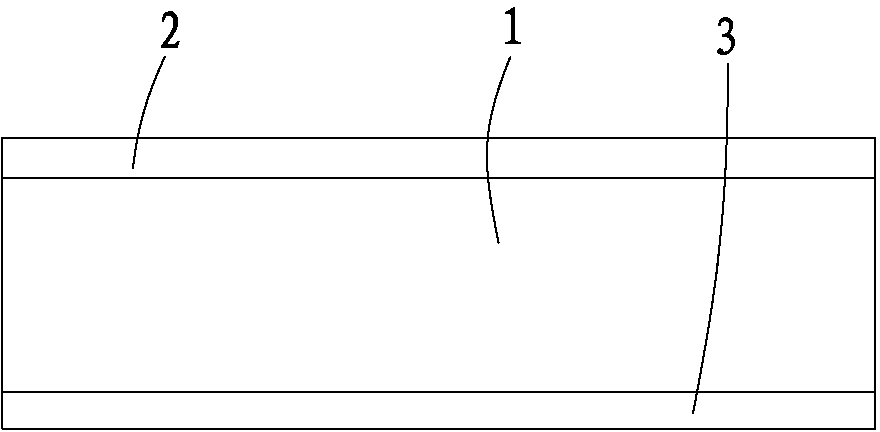
[0019] Example 1, Such as figure 1 As shown, a lithium-ion battery positive electrode current collector structure includes an aluminum alloy layer 1 and an aluminum layer coated on the aluminum alloy layer 1, the aluminum layer includes a first aluminum layer 2 and a second aluminum layer 3, and the aluminum alloy layer 1 is set between the first aluminum layer 2 and the second aluminum layer 3 .

[0020] The first aluminum layer 2 covers the upper surface and the periphery of the aluminum alloy layer 1 , and the second aluminum layer 3 covers the lower surface of the aluminum alloy layer 1 .

[0021] The tensile strength of the aluminum alloy layer 1 is 260MPa, the thicknesses of the first aluminum layer 2 and the second aluminum layer 3 are both 0.5um, and the thickness of the aluminum alloy layer 1 is 8um. Lithium cobaltate was used as the positive electrode material in this example, and the positive electrode slurry was prepared by stirring according to the positive ele...

Embodiment 2

[0024] Example 2, The difference from Embodiment 1 is that in this embodiment, the first aluminum layer 2 is coated on the upper surface of the aluminum alloy layer 1 , and the second aluminum layer 3 is coated on the lower surface and the periphery of the aluminum alloy layer 1 .

[0025] The tensile strength of the aluminum alloy layer 1 is 300 MPa, the thickness of the first aluminum layer 2 and the second aluminum layer 3 are both 2um, and the thickness of the aluminum alloy layer 1 is 15um.

[0026] Others are the same as in Embodiment 1 and will not be repeated here.

Embodiment 3

[0027] Example 3, The difference from Example 2 is that the tensile strength of the aluminum alloy layer 1 in this example is 250 MPa, the thickness of the first aluminum layer 2 and the second aluminum layer 3 are both 1.5um, and the thickness of the aluminum alloy layer 1 is 6um.

[0028] Others are the same as in Embodiment 2 and will not be repeated here.


PUM

PropertyMeasurementUnit
tensile strengthaaaaaaaaaa
strengthaaaaaaaaaa
tensile strengthaaaaaaaaaa

Abstract

The invention especially relates to a current collector structure of a positive electrode of a lithium ion battery, which belongs to the technical field of lithium ion batteries. The structure comprises an aluminum alloy layer and an aluminum layer coated over the aluminum alloy layer, wherein the aluminum layer comprises a first aluminum layer and a second aluminum layer, and the aluminum alloy layer is arranged between the first aluminum layer and the second aluminum layer. Compared with an aluminum foil current collector structure with same thickness, the structure provided by the invention has higher strength, so the thickness of the current collector of the positive electrode is reduced, and energy density of the battery is increased; the upper surface and the lower surface of the aluminum alloy layer are respectively coated by the first aluminum layer and the second aluminum layer, so corrosion of the positive electrode to the material of the body of the aluminum alloy layer is prevented, and the problems of crumpling and strip breakage hardly occur. Moreover, the invention also discloses the lithium ion battery.

Description

technical field [0001] The invention belongs to the technical field of lithium-ion batteries, and in particular relates to a lithium-ion battery cathode current collector structure and a battery comprising the structure. Background technique [0002] Due to the increasing integration of electronic components and applications, consumer battery products have more and more urgent requirements for the energy density and battery performance of lithium-ion batteries. In order to increase the energy density of lithium-ion batteries, lithium-ion battery manufacturers are trying to reduce the thickness of aluminum foil, so as to squeeze out extra space inside the battery to place more active materials. However, as the thickness of the aluminum foil decreases, the overall strength of the aluminum foil will also decrease accordingly, resulting in easy wrinkling and broken tapes during the coating and cold pressing process, which affects normal mass production applications. [0003] In...

Claims


Application Information

Patent Timeline
Patent Type & Authority Applications(China)
IPC IPC(8): H01M4/66H01M10/0525
CPCY02E60/122Y02E60/10
Inventor 李白清张盛武游从辉张柏清
Owner DONGGUAN AMPEREX TECH
Why Eureka
Try Eureka