A pulping control circuit of a cordless soybean milk machine
A cordless soya-bean milk maker and control circuit technology, which is applied in fields such as excitation or armature current control, dairy products, beverage preparation devices, etc., can solve the problems of high instantaneous power of the motor, complex structure, waste of industrial manufacturing costs, etc., and achieve industrial manufacturing Simple, simple control circuit, satisfying the effect of portability
- Summary
- Abstract
- Description
- Claims
- Application Information
AI Technical Summary
Problems solved by technology
Method used
Image
Examples
Embodiment 1
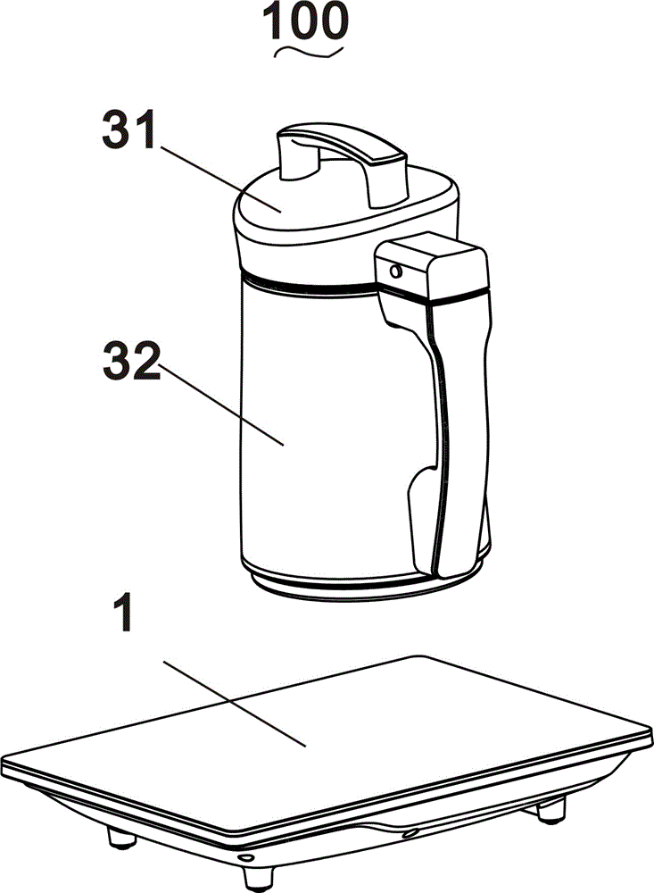
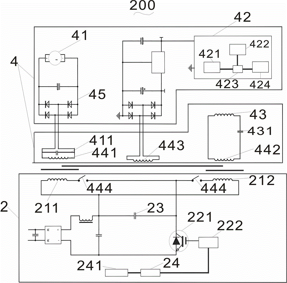
[0035] Such as Figure 1~2Shown is the three-dimensional view of the cordless soybean milk machine 100 and the circuit diagram of the pulping control circuit 200 in the first embodiment of the invention. The machine body includes a machine head 31 and a cup body 32. On the cup body 32 , the motor 41 is connected to the magnetized winding 44 through an electromagnetic coupler. The electromagnetic coupler includes an upper coupler and a lower coupler, the upper coupler is connected with the motor 41 , and the lower coupler is connected with the magnetized winding 44 . The cup body 32 of the soymilk maker of the present invention does not need to separately install a power cord plug, which reduces safety hazards such as electric leakage and machine burn-in. At the same time, the electromagnetic heating coil 44 in the cup body 32 of the soymilk maker has a low calorific value and does not need additional ventilation and heat dissipation holes. The overall water resistance is bett...
Embodiment 2
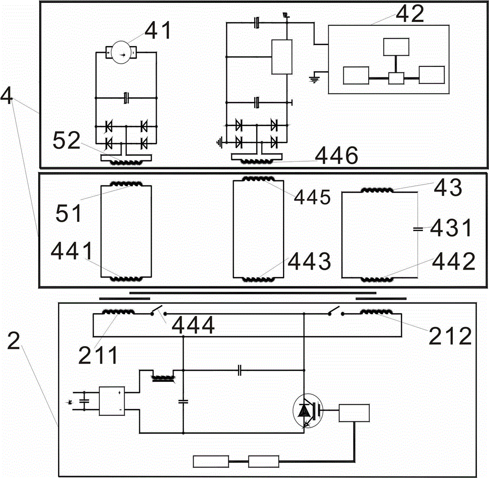
[0042] Such as image 3 Shown, its difference with embodiment one is:
[0043] The lower coupler is provided with a motor energy transmission coil 51 connected to the first coupling coil 441, the motor energy transmission coil 51 is installed in the cup body 32, and the upper coupler is provided with a motor secondary coupling coil 52 for supplying power to the motor 41. The motor secondary coupling coil 52 is coupled with the motor energy transmission coil 51 to obtain electric energy.
[0044] The aforementioned second coupling coil 442 is connected in series with the power supply energy transmission coil 445, the power supply energy transmission coil 445 is arranged in the cup body 32, and the second power supply energy transmission coil 446 coupled with the power supply energy transmission coil 445 is arranged in the handpiece 31. The two power supply energy transfer coils 446 are connected to the signal detection module 42 and supply power thereto. In this embodiment, b...
Embodiment 3
[0046] Such as Figure 4 Shown, its difference with embodiment two is:
[0047] The road of execution comprises motor voltage detection circuit 46, and motor voltage detection circuit 46 is arranged in the head 31, and motor 41 motor voltage detection circuit 46 is set in the head 31, and motor voltage detection circuit 46 is connected with signal detection module 42, and passes signal The detection module 42 transmits the motor signal to the controller 24 in the base body 1 , and the motor voltage detection circuit 46 can control the motor switch 461 to close to control the operation of the motor 41 .
[0048] The exciting winding 21 is an integral coil, and the corresponding magnetizing winding 44 is an integral coil. The electromagnetic heating coil 43 is connected with the magnetizing winding 44 and used for electromagnetic heating. The electromagnetic heating coil 43 is connected with the heating control switch 432. There is a central control module 47 for controlling th...
PUM
 Abstract
Description
Claims
Application Information
 - R&D
- Intellectual Property
- Life Sciences
- Materials
- Tech Scout
- Unparalleled Data Quality
- Higher Quality Content
- 60% Fewer Hallucinations
Browse by: Latest US Patents, China's latest patents, Technical Efficacy Thesaurus, Application Domain, Technology Topic, Popular Technical Reports.
© 2025 PatSnap. All rights reserved.Legal|Privacy policy|Modern Slavery Act Transparency Statement|Sitemap|About US| Contact US: help@patsnap.com


