
Efficient lathe

A machine tool, high-efficiency technology, used in metal processing machinery parts, large fixed members, maintenance and safety accessories, etc., can solve the problems of low processing accuracy and efficiency, and achieve the effect of high processing accuracy, good rigidity and flexible design

Inactive Publication Date: 2013-11-13
迪莱姆数控机电(杭州)有限公司
View PDF10 Cites 1 Cited by
  • Summary
  • Abstract
  • Description
  • Claims
  • Application Information

AI Technical Summary

Problems solved by technology

[0004] The purpose of the present invention is to solve the problems existing in the prior art and provide a high-efficiency machine tool that can reduce the problems of low machining accuracy and low efficiency caused by tool replacement and repeated positioning.

Method used


Image

  • Efficient lathe
  • Efficient lathe

Examples


Embodiment 1)

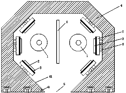
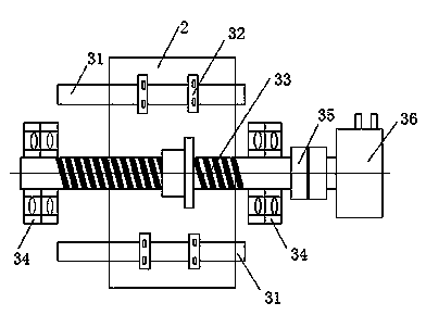
[0033] See figure 1 , a kind of high-efficiency machine tool of the present embodiment, comprises the spindle 1 that is arranged on the machine tool frame to clamp the workpiece and drive the workpiece to rotate, the workbench 2 for placing the tool, the workbench transmission mechanism 3 that provides the moving power for the workbench 2, Assembly frame 4, isolation board 6, carriage 7 and carriage transmission mechanism 8 that provides moving power for carriage 7.

[0034] There are two main shafts 1, which are arranged in parallel, and three worktables 2, three worktable transmission mechanisms 3, three carriages 7 and three carriage transmission mechanisms 8 are arranged around each main shaft 1, so that the main shaft 1 is surrounded trend. In order to reduce the vibration and mutual interference between the left and right spindles during cutting, the two spindles 1 can be placed on different bed bases; or the two spindles 1 can be set on the mineral casting base. A chu...


PUM


Abstract

The invention discloses an efficient lathe comprising spindles arranged on a lathe rack for clamping a workpiece and driving the workpiece to rotate, worktables for placing cutters, and worktable transmission mechanisms for providing power for the worktables; the two spindles are arranged in parallel; at least two worktables and two worktable transmission mechanisms are arranged around each spindle; the distances between the table tops of all worktables to the axes of the corresponding spindles are equal; and the worktables do not interfere with each other in the stroke. The at least two worktables are arranged at the periphery of each spindle, the processing on complex parts needing multiple processing procedures is realized, and at least two cutters can be used for processing one workpiece at the same time, so the processing efficiency is greatly improved, the precision is greatly improved and the processing stability is good.

Description

technical field [0001] The invention relates to a high-efficiency machine tool for machining parts. Background technique [0002] On a common machine tool, there is only one fixed main shaft, and the tool box has a longitudinal and horizontal double-layer structure and a corresponding transmission system. When the tool holder moves tools parallel to the main shaft axis, it can complete cylindrical processing. The end face processing can be completed when the plane tool is used, but the machining efficiency of this machine tool is low, the workpiece fixture is replaced frequently, and the tool system is complicated. [0003] With the improvement of technology, there have been machine tools with double spindles, and the two spindles are arranged in parallel or opposite to each other. For example, the "Double Tool Seat Double Spindle Machine Tool" disclosed in Chinese patent 201220420449.X includes a bed with a main bed head box and the main tool seat arranged on one side of ...

Claims


Application Information

Patent Timeline
Patent Type & Authority Applications(China)
IPC IPC(8): B23Q1/64B23Q11/08B23Q1/01
Inventor 吴承龙
Owner 迪莱姆数控机电(杭州)有限公司
Learn More