Method and device for fitting touch control display panel

A technology for touch display panels and bonding devices, which is applied in lamination devices, chemical instruments and methods, instruments, etc., and can solve problems affecting the production capacity of bonding processing, high defect rate, and inability to cover side areas

Inactive Publication Date: 2013-11-13
MARKETECH INT
View PDF3 Cites 2 Cited by
  • Summary
  • Abstract
  • Description
  • Claims
  • Application Information

AI Technical Summary

Problems solved by technology

[0004] However, the bonding of the first transparent substrate 5 and the second transparent substrate 6 in the above-mentioned manner has the following disadvantages in actual manufacturing: the controllability of the diffusion of the aUV glue 8 is positively correlated with the feed speed of the first positioning mechanism 71 , that is, the faster the feed speed of the first positioning mechanism 71, the more difficult it is to control the diffusion speed of the UV glue 8, and if the feed speed is reduced, it will take more time to wait for the UV glue 8 to diffuse, which will relatively affect the sticking process. The production capacity of combined processing; b ultraviolet light emitting device 73 emits ultraviolet light on the diagonal line half the distance between the center point and the end point, however, because the UV glue 8 still has a certain distance to diffuse to the entire substrate, its diffusion speed is difficult to control, which is easy to cause The UV glue 8 overflows between the first transparent substrate 5 and the second transparent substrate 6, resulting in an excessively high defect rate, or the situation that some side areas cannot be fully covered, thereby affecting the bonding quality of the touch display panel

Method used


Image

  • Method and device for fitting touch control display panel
  • Method and device for fitting touch control display panel
  • Method and device for fitting touch control display panel

Examples


Embodiment Construction

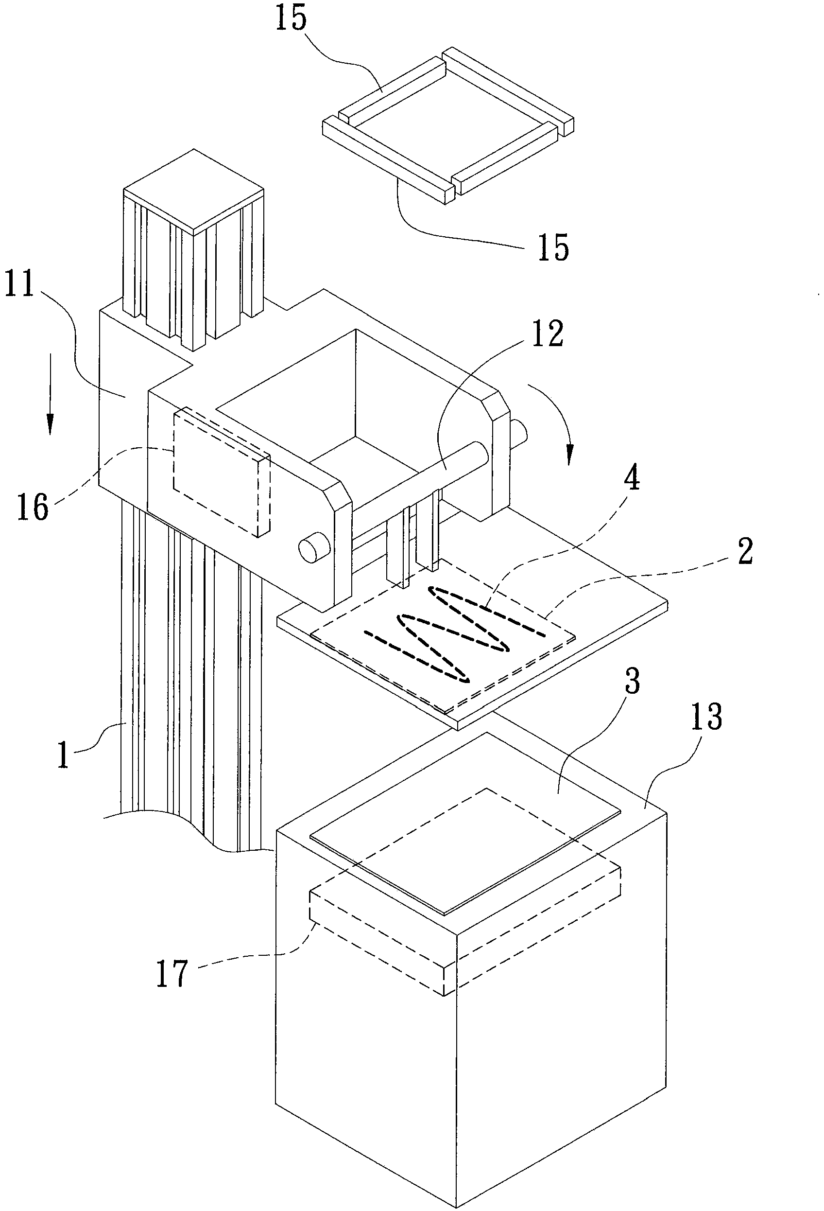
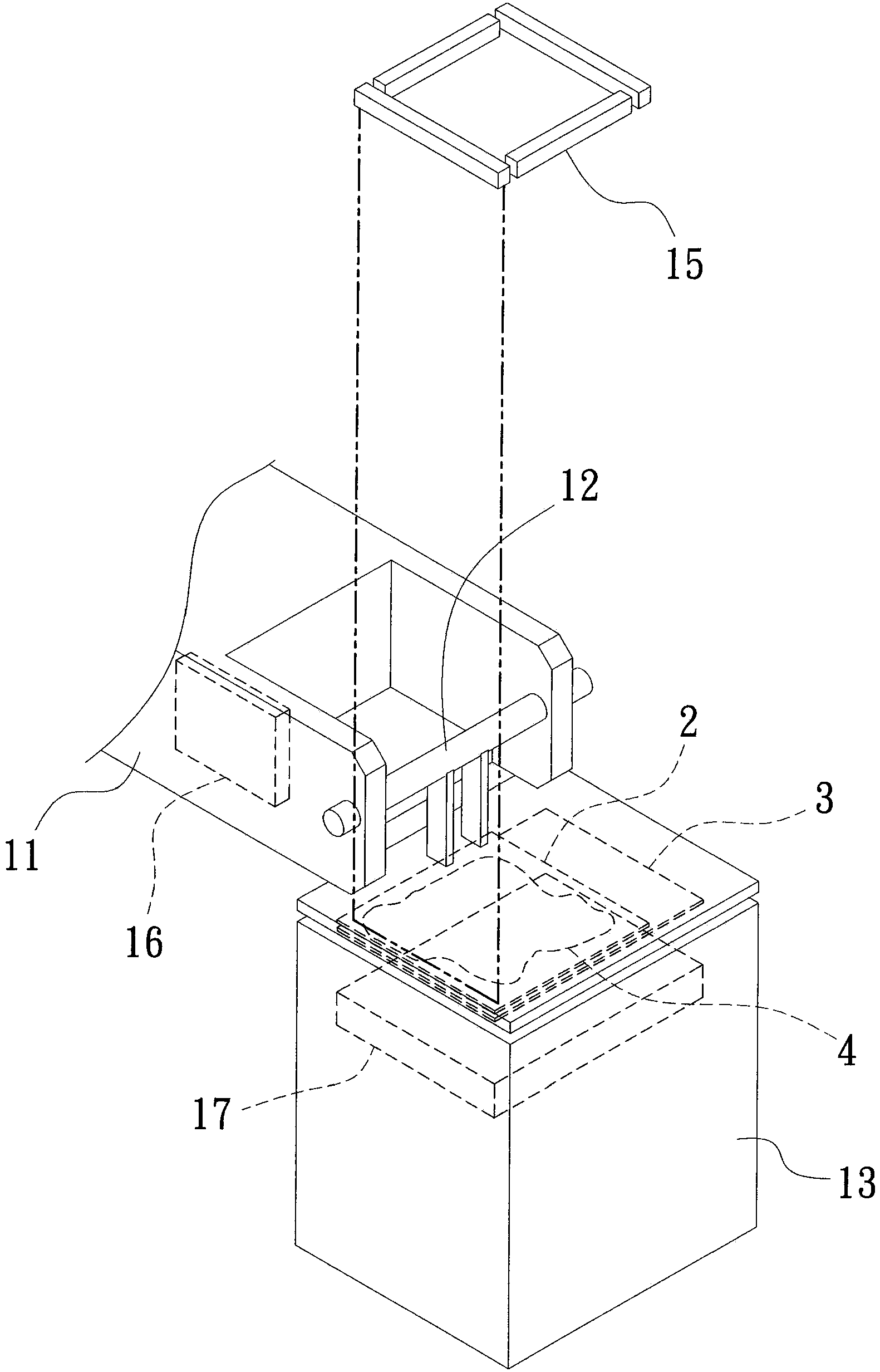
[0031] First, see figure 1 As shown, it is a preferred embodiment of the touch display panel bonding device of the present invention, which mainly includes:

[0032] a base 1;

[0033] A lifting device 11, set on the base 1;

[0034] A first positioning mechanism 12 is pivotally arranged on the lifting device 11, and a first workpiece 2 is fixed on it through the first positioning mechanism 12; wherein, the first positioning mechanism 12 can fix the first workpiece 2 on it by vacuum adsorption superior;

[0035] A second positioning mechanism 13 is arranged on the base 1, and a second workpiece 3 is fixed on it through the second positioning mechanism 13; wherein, the second positioning mechanism 13 can also fix the second workpiece 3 on it by means of vacuum adsorption. Above, the procedure for adjusting the alignment with the first workpiece 2;

[0036] A coating mechanism 14 is arranged on the base 1, and the coating mechanism 14 can coat the adhesive material 4 on a p...


PUM


Abstract

The invention relates to a method and a device for fitting a touch control display panel. The method comprises the following steps of: coating an adhesive material on a preset position of a first workpiece by a coating mechanism; then adhering a surface with the adhesive material of the first workpiece to a second workpiece; then, driving a first positioning mechanism pivoting on a lifting device to move downwards by the lifting device, so as to oppress the first workpiece towards the second workpiece; and carrying out a curing operation through at least one curing device above a side edge of the second workpiece when the adhesive material spreads to a side edge of the first workpiece. Therefore, the earlier the adhesive material spreads to the side edge of the first the workpiece, the sooner it is cured; and the method and the device can improve the phenomenon that difficult control on the diffusion velocity of a traditional adhesive material leads to the problems of overflow from the workpiece and incapability of full spreading.

Description

technical field [0001] The present invention relates to a touch display panel lamination method and its device, in particular to a method that can accelerate the diffusion speed of adhesive materials, so as to greatly reduce the lamination operation time and increase production capacity, and at the same time avoid that the diffusion speed of adhesive materials is difficult to control A bonding method and device for a touch display panel that cause overflow of workpieces or situations that cannot be filled. Background technique [0002] Generally speaking, a touch display panel includes a first transparent substrate and a second transparent substrate. In actual production and manufacturing, the first transparent substrate can be the protective layer (Cover Lens / Cover Glass, etc.) The second transparent substrate can be an optical sheet such as a polarizer and a color filter inside the current liquid crystal display panel, or an isolation layer or a touch cell inside the touch...

Claims


Application Information

Patent Timeline
Patent Type & Authority Applications(China)
IPC IPC(8): B32B37/12G06F3/041
Inventor 陈典廷伍明华郭绮彬
Owner MARKETECH INT
Why Eureka
Try Eureka