
Large steam turbine blade trimming hydraulic press

A technology for steam turbine blades and hydraulic presses, which is applied in the field of hydraulic machinery, can solve the problems of harsh working environment of operators, affecting the production efficiency of production lines, and workers being unable to work for a long time, so as to meet the requirements of modern production, easy maintenance of structure and guarantee of machining performance. Effect

Active Publication Date: 2016-08-31
TIANJIN TIANDUAN PRESS CO LTD
View PDF8 Cites 0 Cited by
  • Summary
  • Abstract
  • Description
  • Claims
  • Application Information

AI Technical Summary

Problems solved by technology

However, most of the flash generated by trimming will be bonded to the punch on the press, making it difficult to separate
At present, the separation of molded parts and flash edges is mainly carried out manually. However, since the molded parts and flash edges after die forging are both hot parts, the operating environment temperature is high, resulting in harsh working conditions for operators and high labor intensity, which seriously affects productivity
In addition, because the feeding device of the traditional die forging press is located under the slider, and the temperature of the workpiece is too high, it is easy to cause hidden dangers such as frequent oil leakage and heat loss in the feeding system
[0005] When the blade is die-forged, because the flash is on the outside of the formed part, the manipulator cannot accurately remove the flash, and it is easy to take out the formed part together with the flash. The removal of the flash and the formed part affects the work the beat
If manual separation is used, due to the high ambient temperature around the press and the high labor intensity, workers cannot work for a long time, which seriously affects the production efficiency of the production line

Method used


Image

  • Large steam turbine blade trimming hydraulic press
  • Large steam turbine blade trimming hydraulic press
  • Large steam turbine blade trimming hydraulic press

Examples


Embodiment Construction

[0041] In order to further understand the invention content, characteristics and effects of the present invention, the following examples are given, and detailed descriptions are as follows in conjunction with the accompanying drawings:

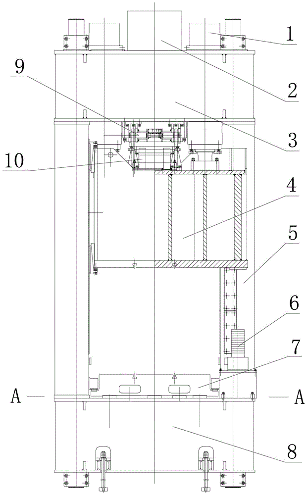
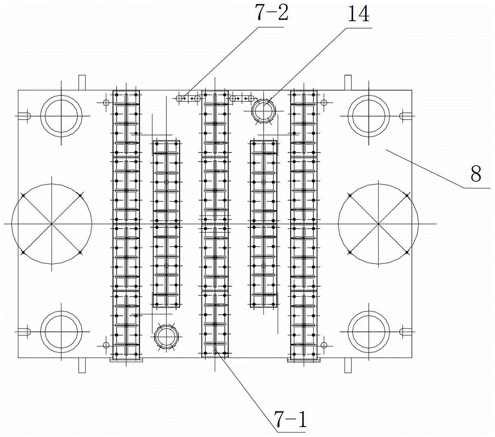
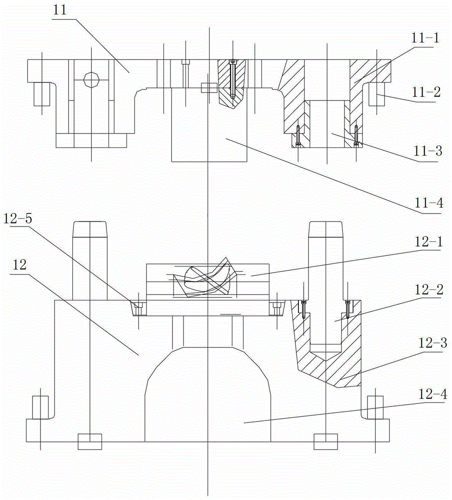
[0042] see figure 1 and figure 2 , a large steam turbine blade trimming hydraulic press, including a fuselage formed by four pillars 5, an upper beam 3 and a lower beam 8 fastened by a lock nut, and a master cylinder 2 and a return cylinder 1 are installed on the upper beam, and the master cylinder and The lower part of the return cylinder is fixedly connected with the slide block 4, and the movable workbench 7 is installed on the lower beam, which also includes a trimming upper die 11 connected with the slide block, a trimming lower die 12 installed on the movable workbench, and a trimming lower die 12 installed on the machine. The buffer cylinder 6 at the middle position of the front and rear pillars on both sides of the body can effectiv...


PUM


Abstract

The invention relates to a large turbine blade reshaping and trimming hydraulic machine which comprises a machine body formed by four struts, an upper cross beam and a lower cross beam. A main cylinder and a return cylinder are installed on the upper cross beam. A sliding block is fixedly connected to the lower portion of the main cylinder. A shuttle table is installed on the lower cross beam. The large turbine blade reshaping and trimming hydraulic machine is characterized by further comprising an upper trimming die and a lower trimming die, wherein the upper trimming die is connected with the sliding block, the lower trimming die is installed on the shuttle table, upper ramming devices are installed at four corners of the upper end of the sliding block, a discharging device is arranged on the upper end face of the shuttle table, a shuttle table positioning device is fixedly installed inside the lower cross beam, and cushion cylinders are installed at the positions between the front struts and the rear struts on the two sides of the machine body. The large turbine blade reshaping and trimming hydraulic machine has the advantages of preventing a worker from operation in a high-temperature severe environment, being capable of reducing labor intensity, and safe and reliable in die change operation, bringing convenience to fast separation of trimming waste and automatic discharging, ensuring accurate positioning of the shuttle table, and being capable of improving the product quality and production efficiency substantially, thereby meeting the requirement for modernization of turbine blade production.

Description

technical field [0001] The invention belongs to the technical field of hydraulic machinery, in particular to a large steam turbine blade shaping and trimming hydraulic machine. Background technique [0002] Steam turbine is the main prime mover of modern thermal power plants and nuclear power plants. It can also be used as propulsion power for large ships and warships, as well as various large working machines driven by metallurgy, chemical industry and other industries. The blade is an important component of the steam turbine. The traditional processing method of the steam turbine blade is mostly cast and then processed by a press, and the mold structure of the press processing equipment is generally fixed with the lower end of the upper punch and the upper die seat. When the punch needs to be replaced When disassembling, the operator needs to remove the fixing screw from below. In order to prevent the upper punch from falling during disassembly, the upper punch needs to be...

Claims


Application Information

Patent Timeline
Patent Type & Authority Patents(China)
IPC IPC(8): B21D28/14B21J9/12
Inventor 武健
Owner TIANJIN TIANDUAN PRESS CO LTD
Learn More