Supercharge Your Innovation With Domain-Expert AI Agents!

Device for compressing and releasing engine braking

An engine braking and motion technology, applied in the directions of engine components, machines/engines, valve devices, etc., can solve the problems of large oil pressure in the hydraulic system, and achieve the effects of increased height, reliable structure and convenient layout

Active Publication Date: 2013-11-20
HUBEI AUSTRIAN ABSORBER MFG
View PDF10 Cites 6 Cited by
  • Summary
  • Abstract
  • Description
  • Claims
  • Application Information

AI Technical Summary

Problems solved by technology

The disadvantage of this structure is that the hydraulic system bears a large oil pressure

Method used


Image

  • Device for compressing and releasing engine braking
  • Device for compressing and releasing engine braking
  • Device for compressing and releasing engine braking

Examples


Embodiment Construction

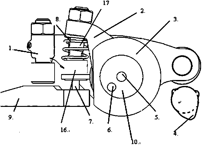
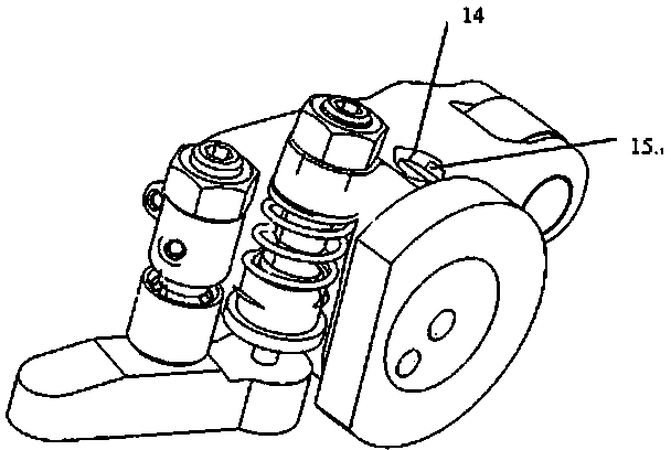
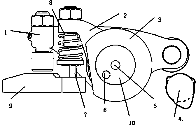
[0021] Such as figure 1 , image 3 , Figure 7 , Figure 8 The shown compression release engine brake device includes a main rocker arm 1, an auxiliary rocker arm 2, a fixed disc 3, a rocker arm shaft 10 with two oil passages, and two actuator piston assemblies 11 1. A camshaft 4, the rocker arm shaft 10 is fixed on the fixed plate 3, the main rocker arm 1 and the auxiliary rocker arm 2 are swingably installed on the rocker arm shaft 10, an oil passage (lubricating oil passage 5) of the rocker arm shaft To lubricate the rocker shaft, the other oil passage (executive oil passage 6) of the rocker shaft is a power oil passage controlled by a solenoid valve, which is used to drive the actuator piston assembly; two actuator piston assemblies 11 are evenly arranged on the fixed plate Above, one end of the piston rod of the actuator piston assembly 11 has a thread, which is directly connected with the auxiliary rocker arm 2, and the cylinder body of the actuator piston assembly an...


PUM


Abstract

The invention discloses a device for compressing and releasing engine braking. The device has a reliable structure, is convenient to arrange in structure and does not increase the height of an engine. The technical essentials of the device are as follows: a primary rocker arm and a secondary rocker arm are mounted on a rockshaft in an oscillating manner; the rockshaft is fixed on a fixed disc; two piston actuating assemblies are uniformly arranged on the fixed disc; the piston rod of one piston actuating assembly is directly linked with the secondary rocker arm; the cylinder body of one piston actuating assembly is in interference linkage with the inner hole of the fixed disc; the elephant foot position at the front end of the primary rocker arm and the elephant foot position at the front end of the secondary rocker arm correspond to the upper surface of an air valve yoke and the brake pushrod on the air valve yoke respectively; a cam shaft is arranged at the tail end of the primary rocker arm; two small bosses are arranged on the cam molded lines of the cam shaft; the tooth form linkage manner of the primary rocker arm and the secondary rocker arm is controlled through the piston actuating assemblies; when the engine braking does not work, the primary rocker arm is in contact with the secondary rocker arm through only one tooth; when the engine braking works, the primary rocker arm is in contact with the secondary rocker arm through multiple teeth.

Description

technical field [0001] The invention relates to the fields of machinery and internal combustion engines, in particular to a valve driving mechanism in the field of air management of internal combustion engines, in particular to a compression release engine braking device. Background technique [0002] There are two structural forms of engine braking, compression release and deflation. The compression release type brake is to open the exhaust valve before the end of the compression stroke of the four-stroke engine, and the exhaust valve is opened until the early stage of the expansion stroke. A brake of the compression release type is described in US Patent No. 3,220,392 by Cummins of the United States in 1965. This patent describes the action process of this braking system. The system is a hydraulic system, including the main piston and the auxiliary piston. The movement of the main piston is driven by a special cam or the exhaust cam of the adjacent cylinder. The valve i...

Claims


Application Information

Patent Timeline
IPC IPC(8): F01L13/06F01L9/02F01L9/11
Inventor 刘莎伍长彬
Owner HUBEI AUSTRIAN ABSORBER MFG
Features
  • R&D
  • Intellectual Property
  • Life Sciences
  • Materials
  • Tech Scout
  • Unparalleled Data Quality
  • Higher Quality Content
  • 60% Fewer Hallucinations
Learn More