Magnetic coupler

A magnetic coupler, permanent magnet technology, applied in electrical components, electromechanical devices, electromechanical transmission devices, etc., can solve the problem of reducing the magnetic flux density of the air gap magnetic field, increasing the air gap size of the permanent magnet rotor and the squirrel cage rotor, and improving the execution efficiency. It can simplify the analysis and calculation of the magnetic circuit, facilitate precise control, and improve the heat dissipation conditions.

Active Publication Date: 2013-11-20
DALIAN JIAOTONG UNIVERSITY
View PDF10 Cites 21 Cited by
  • Summary
  • Abstract
  • Description
  • Claims
  • Application Information

AI Technical Summary

Problems solved by technology

However, this patented technology is mainly used in the transmission device or equipment that requires no leakage in the production environment. An isolation sleeve is installed between the permanent magnet rotor and the squirrel cage rotor to increase the air gap between the permanent magnet rotor and the squirrel cage rotor. The size and the increase of the air gap lead to an increase in the loss of the magnetomotive force in the air, which reduces the magnetic flux density of the air gap magnetic field. Compared with the permanent magnet of the same volume, its energy conversion efficiency is low, and the torque that can be transmitted is reduced. Small, large permanent magnet magnetic potential loss, low execution efficiency
[0009] The permanent magnet asynchronous magnetic transmission device represented by the US patent (Pub.No.: US2010 / 0277021A1) also uses a squirrel cage rotor in the form of an asynchronous motor. There is no spacer between the permanent magnet rotor and the squirrel cage rotor, so its The air gap flux density is large, the flux leakage is small, and the execution efficiency is high. However, the squirrel cage rotor of the asynchronous motor used is a non-standard structure and needs to be redesigned. Not only the design cycle is long, but also the process and molds need to be re-customized, which increases manufacturing cost

Method used


Image

  • Magnetic coupler
  • Magnetic coupler
  • Magnetic coupler

Examples


Embodiment Construction

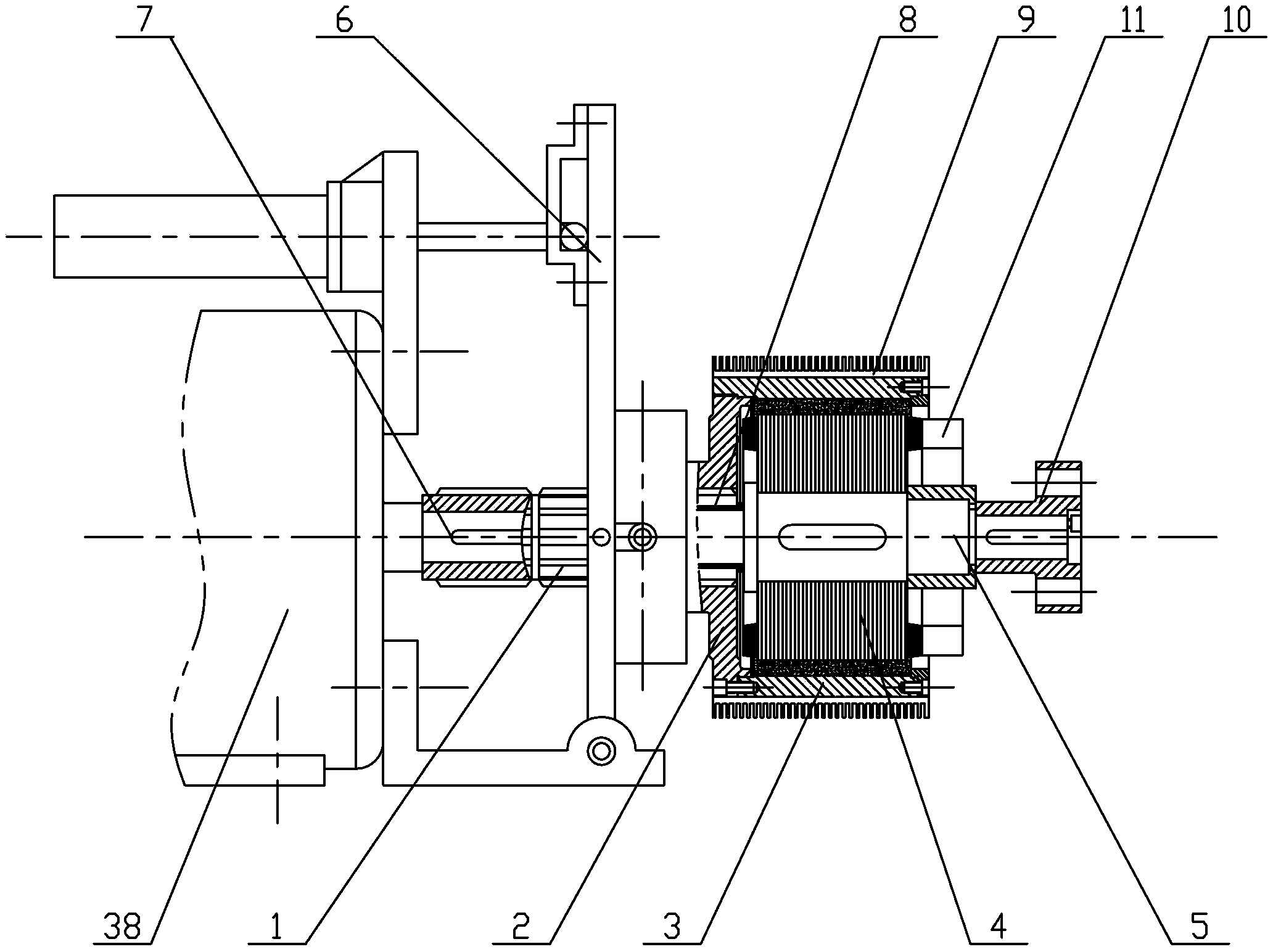
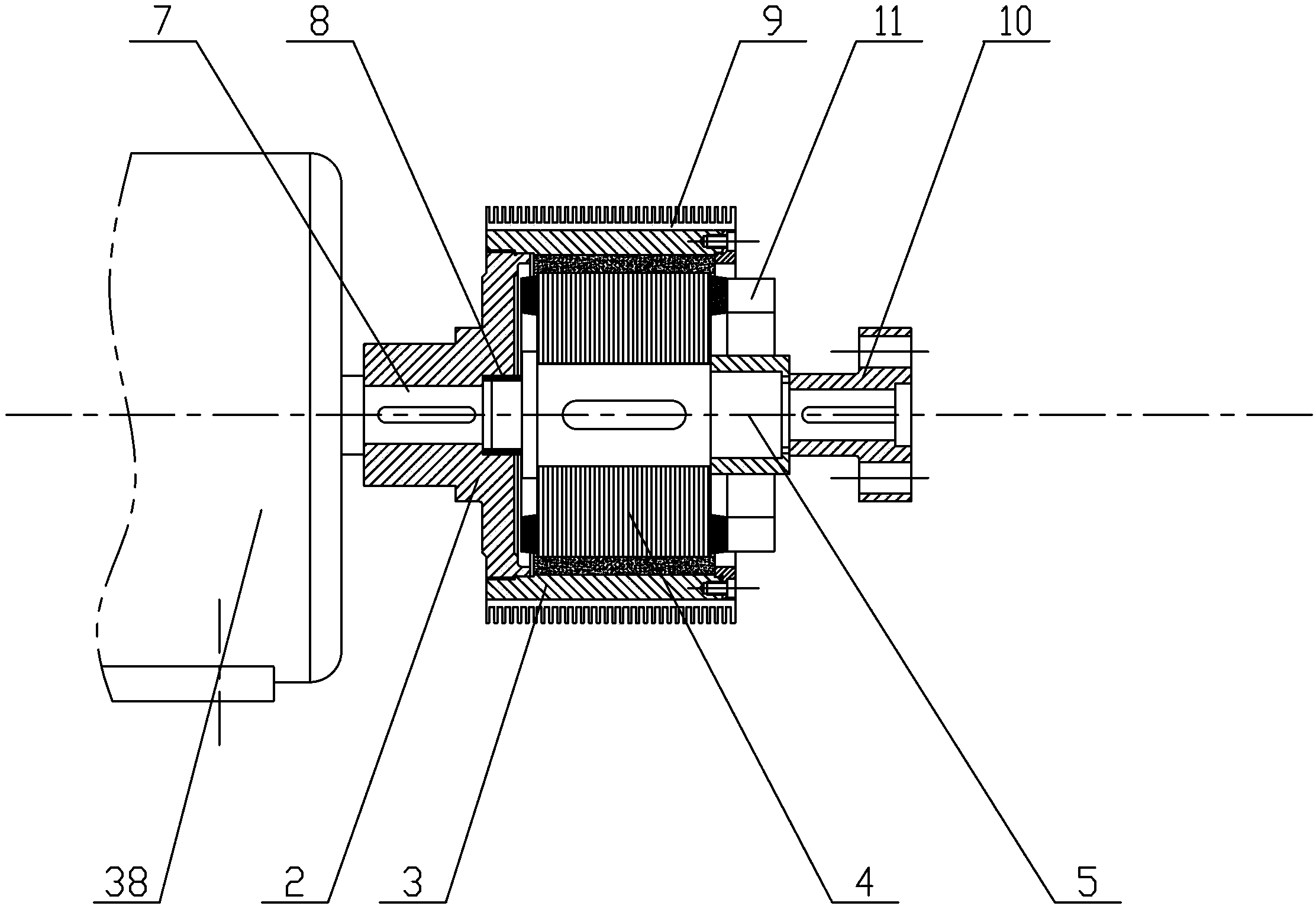
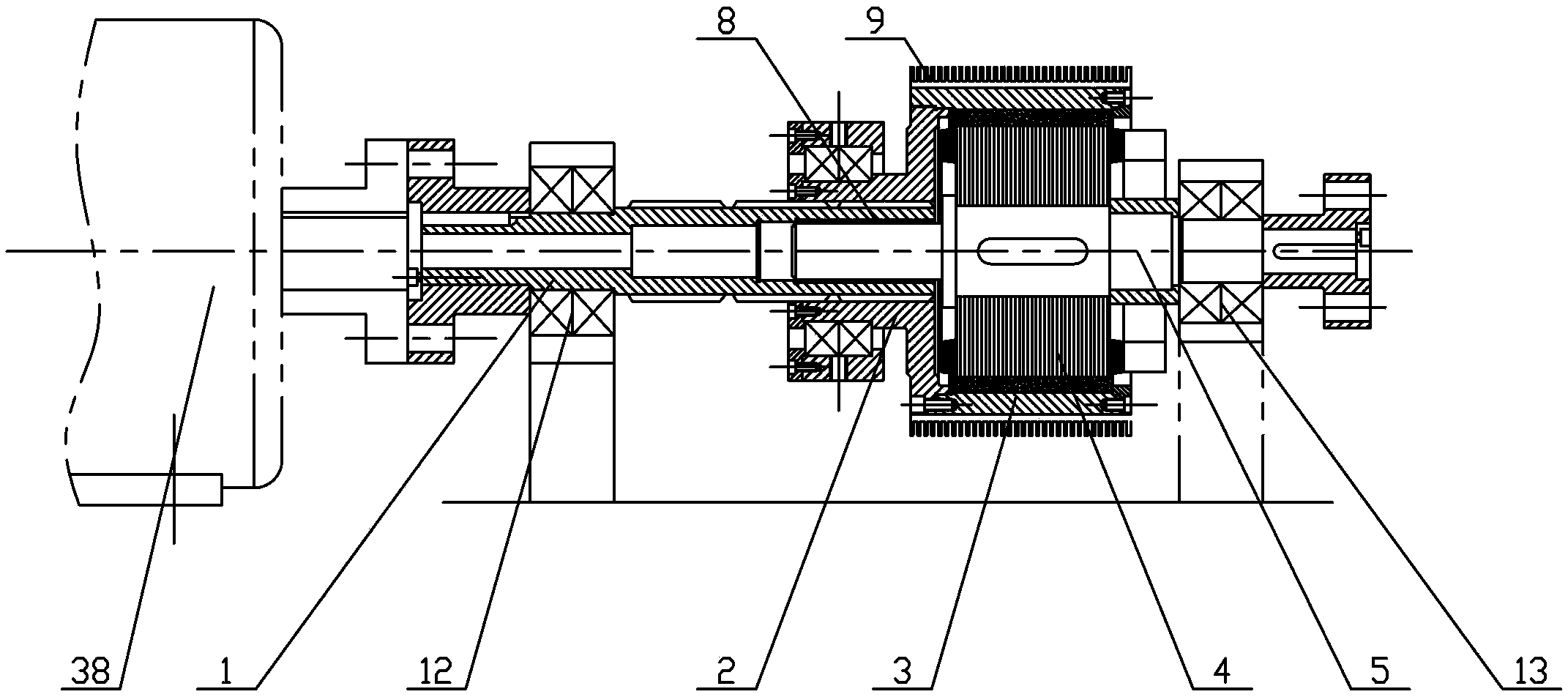
[0060] The present invention will be described in further detail below in conjunction with the accompanying drawings.

[0061] The basic structure of the present invention is as figure 1 As shown: the power output shaft 7 of the prime mover transmits the power torque to the power input shaft 1 of the magnetic coupling through a key connection, and the power input shaft 1 is an external spline structure, and the power torque is transmitted to the coupling method by using the spline connection Lan 2 and permanent magnet external rotor assembly 3, permanent magnet external rotor assembly 3 and prime mover power output shaft 7 rotate synchronously. There is a uniform air gap between the outer surface of the cage inner rotor 4 and the inner surface of the permanent magnet outer rotor assembly 3 . Due to the rotation of the permanent magnet outer rotor assembly 3, a rotating magnetic field is generated in the air gap, and an induced current is generated in the guide bars in the ca...


PUM


Abstract

The invention discloses a magnetic coupler which comprises a power input shaft, connecting flanges, permanent magnet outer rotor assemblies, cage type inner rotors, a power output shaft and a mechanical speed adjustment device, wherein the permanent magnet outer rotor assemblies have hollow cup-shaped structures, are sleeved outside the cage-type inner rotors and realize transmission of torque under the coupling action of an air gap magnetic field between the permanent magnet outer rotor assemblies and the cage-type inner rotors; the mechanical speed adjustment device can change axial air gap areas between the permanent magnet outer rotor assemblies and the cage-type inner rotors according to a lever theory, thus realizing stepless speed variation for load rotating speed. According to the magnetic coupler, a method for designing the number of pole pairs of the permanent magnet outer rotor assemblies is provided on the basis of a minimum torque ripple rule, so that the thickness of yokes and the rotating inertia of the coupler are reduced. The cage-type inner rotors can adopt structures which are the same as or similar to that of the conventional motor cage rotor iron core. The magnetic coupler disclosed by the invention can be coaxially connected with a load and can be used as a belt wheel adapter matched with a belt wheel.

Description

technical field [0001] The invention relates to a power mechanical transmission technology, in particular to a magnetic coupling. Background technique [0002] The so-called advanced transmission energy saving refers to the replacement of backward energy-consuming transmission methods with advanced energy-saving transmission methods. Among them, the magnetic coupling drive has excellent functions such as light-load start, overload protection, impact reduction, torsional vibration isolation, etc., so it is applied to large-inertia, difficult-to-start machinery, which can change the backward transmission mode of "big horse-drawn trolley" and save energy significantly. . [0003] Belt transmission is an important form of mechanical transmission and the core connecting part of electromechanical equipment. Its biggest feature is its simple structure, easy replacement and free speed change. [0004] According to statistics, more than 50% of the power transmission form between th...

Claims


Application Information

Patent Timeline
Patent Type & Authority Applications(China)
IPC IPC(8): H02K51/00
Inventor 葛研军杨均悦汤武初周凯凯刘艳龙赵鹏
Owner DALIAN JIAOTONG UNIVERSITY
Why Eureka
Try Eureka