
Semi-automatic electronic block instrument and working method of block instrument

A blocking machine, semi-automatic technology, applied in railway car body parts, railway signals and safety, interlocking devices between switches and signals, etc., can solve the problems of large maintenance workload, poor anti-interference ability, and large workload, etc. Achieve the effect of convenient upgrade and transformation, strong anti-interference ability and small space occupation

Inactive Publication Date: 2013-11-27
NANJING TICOM TECH
View PDF4 Cites 14 Cited by
  • Summary
  • Abstract
  • Description
  • Claims
  • Application Information

AI Technical Summary

Problems solved by technology

[0003] (1) The blocking machine is composed of a relay combination, which takes up a lot of space, and the relay needs to be inspected regularly, and the maintenance workload is heavy;
[0004] (2) Communication between stations of the system is transmitted through cables, which has poor anti-interference ability, and due to difficult cable maintenance, heavy workload, easy aging of cables, natural disasters, theft, construction damage, etc. Larger hidden dangers often cause parking accidents, lower driving efficiency, delays in train time, etc.;
[0005] (3) The system does not reserve an interface for automatic inter-station blocking, and it is difficult to upgrade to automatic inter-station blocking, and the project is complex;
[0006] (4) The system does not have a fault self-diagnosis function, and it is difficult to troubleshoot

Method used


Image

  • Semi-automatic electronic block instrument and working method of block instrument
  • Semi-automatic electronic block instrument and working method of block instrument
  • Semi-automatic electronic block instrument and working method of block instrument

Examples


Embodiment Construction

[0037] The present invention will be further described below in conjunction with accompanying drawing.

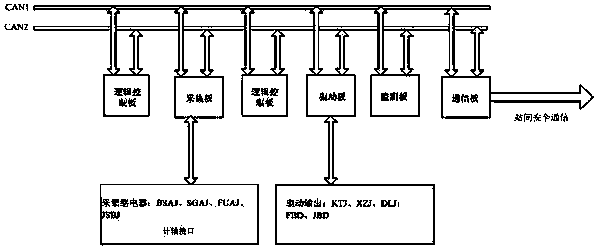
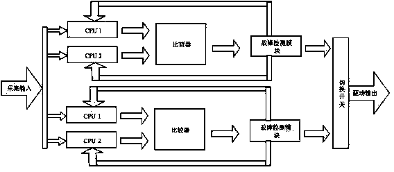
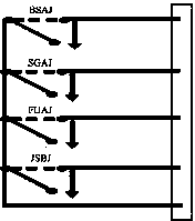
[0038] Such as figure 1 As shown, the present invention is connected by a CAN bus by a communication board, an acquisition board, a driver board, a monitoring board, a communication board and two logic control boards. Such as figure 2 As shown, each logic control board consists of two parallel CPU , a comparator and a fault detection module. The two logic control boards are controlled by a switch, and the two logic control boards form a two-by-two redundant system, which greatly improves the system reliability. The monitoring board communicates with the microcomputer monitoring system, and uploads the working status and alarm information of the equipment to the microcomputer monitoring system, so as to achieve real-time maintenance of the system and accurate fault location.

[0039] image 3 It is a schematic diagram of the acquisition interface circuit. The acquisi...


PUM


Abstract

The invention provides a semi-automatic electronic block instrument and a working method of the block instrument. The block instrument is composed of a communication board, a collection board, a drive board, a monitoring board, a communication board and two logic control boards which are connected via a CAN (Controller Area Network) bus, wherein each logic control board comprises two CPUs (Central Processing Units) which are connected in parallel and a comparer; the collection board is composed of collection relays BSAJ, SGAJ, FUAJ and JSBJ which are connected in parallel; and the monitoring board is connected with a computer monitoring system. The two logic control boards of the block instrument form a double 2-vote-2 redundant system, and seven block signals are transmitted via a cable to realize communication among stations, so that the block instrument occupies a small space, has a stable system, is convenient to mount and is suitable for emergency rescue of railway signals; the block instrument is compatible with an existing railway signal interlock system so that digital communication among the stations is increased; automatic block among the stations is realized via a pre-reserved axle counting interface; the upgrading and reconstruction are convenient; the maintenance is convenient; the system has a self-diagnostic function; and the communication among the stations is realized via the cable so that the communication has strong anti-jamming capability and is difficult to damage.

Description

technical field [0001] The invention relates to the field of railway communication systems, in particular to an electronic semi-automatic blocking machine and its working method. Background technique [0002] Relay semi-automatic blocking has the advantages of simple equipment, tight circuit structure, stable and reliable operation, convenient use, easy maintenance and construction, and low investment. It has been widely used in single-track sections of railways in my country. However, the relay semi-automatic block has the following disadvantages: [0003] (1) The blocking machine is composed of a relay combination, which takes up a lot of space, and the relay needs to be inspected regularly, and the maintenance workload is heavy; [0004] (2) Communication between stations of the system is transmitted through cables, which has poor anti-interference ability, and due to difficult cable maintenance, heavy workload, easy aging of cables, natural disasters, theft, constructi...

Claims


Application Information

Patent Timeline
IPC IPC(8): B61L19/06
Inventor 蔡虎刘余才罗东海吉荣新
Owner NANJING TICOM TECH
Learn More