Calibration apparatus and method for scattering type cloud droplet particle detector

A calibration device and detector technology, applied in the field of meteorological analysis, can solve the problems of reducing the use efficiency of standard particles, different electrical signal widths, unstable particle speeds, etc., to achieve improved particle use efficiency, accurate calibration results, and method step control precise effect

Inactive Publication Date: 2013-11-27
NANJING UNIV OF INFORMATION SCI & TECH
View PDF5 Cites 4 Cited by
  • Summary
  • Abstract
  • Description
  • Claims
  • Application Information

AI Technical Summary

Problems solved by technology

However, there are certain defects in this method, mainly as follows: 1. The speed of the blown particles is unstable, and the average speed of the particles is affected by the canned nitrogen cylinder. The speed of particles is different at each moment, resulting in different widths of electrical signals, which affects data processing; 2. Particle coincidence effect. When the nitrogen cylinder switch is just turned on, the general gas pressure is relatively high, and all standard particles are blown out in a short time. The density of the particles blown out is relatively high, causing multiple standard particles to appear in the optical path at the same time, that is, the receiving system receives the scattering of multiple particles at the same time, and a larger particle diameter will be obtained; 3. During the calibration process, the particles should be from the detector. The sensitive area passes through. There is no corresponding position adjustment structure in the current calibration, and the range of the sensitive area is very small, about 2mm. Therefore, it is difficult to ensure that the particles pass through the sensitive area, which also reduces the use efficiency of standard particles.

Method used


Image

  • Calibration apparatus and method for scattering type cloud droplet particle detector
  • Calibration apparatus and method for scattering type cloud droplet particle detector
  • Calibration apparatus and method for scattering type cloud droplet particle detector

Examples


Embodiment 1

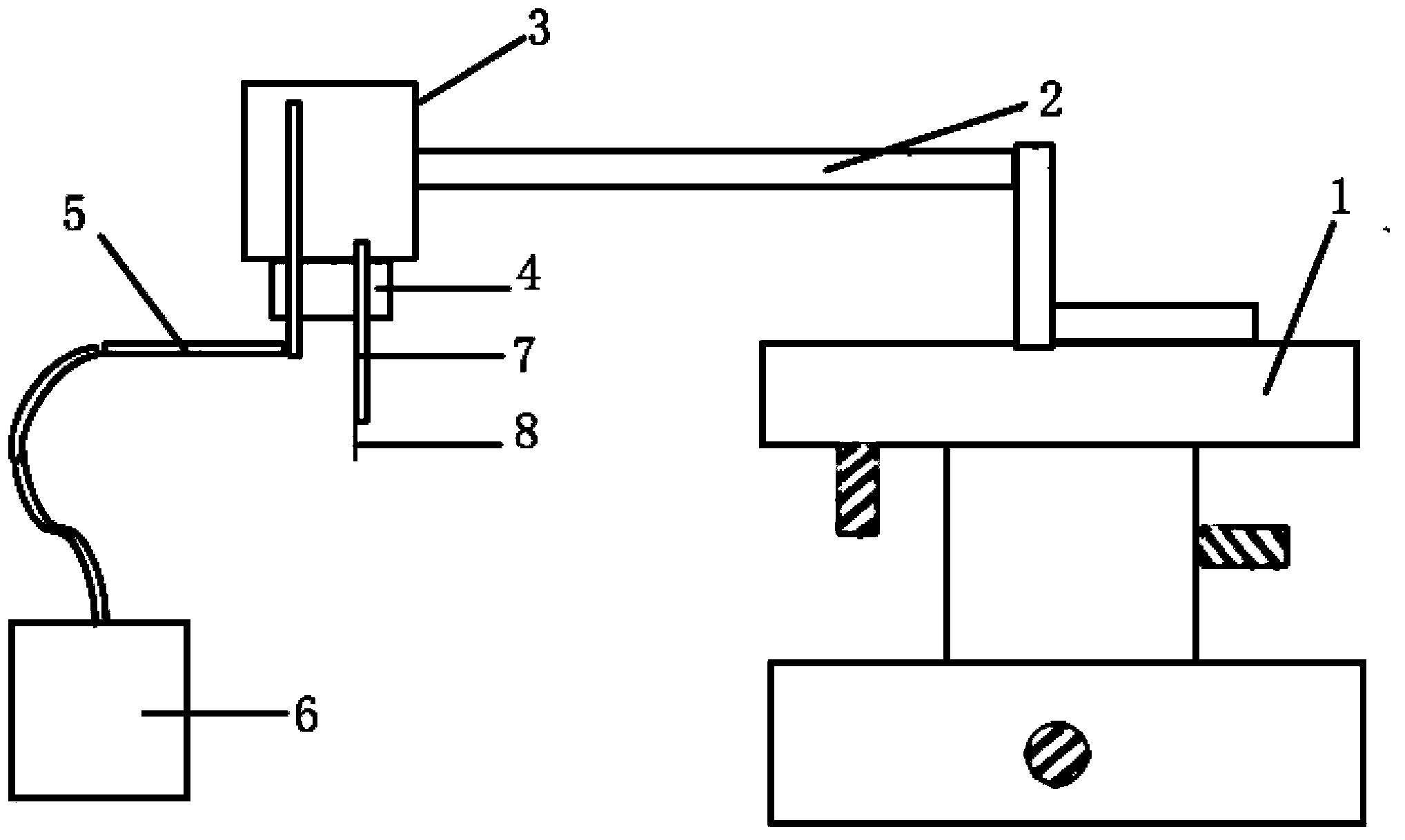
[0027] A calibration device for a scattering cloud droplet particle detector of the present invention, such as figure 1 As shown, it includes a three-dimensional translation stage 1 , a glass bottle 3 for placing standard particles, a constant airflow pump 6 and an optical fiber core 8 .

[0028] The three-dimensional translation stage 1 includes adjustment screws in the three directions of X, Y, and Z, and the adjustment accuracy of the adjustment screws is 20 microns. The table top of the three-dimensional translation platform 1 is fixedly connected with the glass bottle 3 through the connecting piece 2, and by adjusting the adjustment screws in all directions of the three-dimensional translation platform 1, the optical fiber fixed under the glass bottle 3 is located at the center of the cloud droplet particle detector, and through translation The continuous position adjustment of the stage can accurately measure the range of the sensitive area. In this embodiment, the conn...


PUM

PropertyMeasurementUnit
volumeaaaaaaaaaa
lengthaaaaaaaaaa
lengthaaaaaaaaaa

Abstract

The present invention provides a calibration apparatus for a scattering type cloud droplet particle detector, and belongs to the technical field of meteorology analysis. The calibration apparatus comprises a three-dimensional translation table, a glass bottle for placing standard particles, a constant gas flow pump and an optical fiber core, wherein the table surface of the three-dimensional translation table is fixedly connected with the glass bottle, the bottle opening of the glass bottle is connected with a glass bottle cover, the glass bottle cover is provided with a gas inlet pipe and a gas outlet pipe, one end of the gas inlet pipe extends into the bottom of the glass bottle, the other end of the gas inlet pipe is connected with the constant gas flow pump through a pipeline, one end of the gas outlet pipe extends into the upper portion of the glass bottle, and other end of the gas outlet pipe is fixed with the optical fiber core. The present invention further provides a calibration method for a scattering type cloud droplet particle detector. The calibration method comprises determining a center position, calculating a sensitivity area, drawing an amplitude and frequency distribution map, and drawing a cloud droplet particle detector characteristic response curve. With the present invention, problems of different speeds, internal superposition of sensitivity areas, and the like during a calibration process are avoided, it is ensured that particles pass through the sensitivity area, and use efficiency of particles is increased.

Description

technical field [0001] The invention relates to a calibration device of a cloud drop particle detector, in particular to a calibration method and device of a scattering cloud drop particle detector using an optical fiber core to measure a sensitive area, and belongs to the technical field of meteorological analysis. Background technique [0002] The cloud droplet particle detector can be used to measure the particle size spectrum and water content of cloud droplet particles, and its measurement data has an important guiding role in artificial weather modification, which is conducive to improving the efficiency of artificial activities. During the measurement, the detector is fixed under the wing of the aircraft. When the aircraft flies in the cloud, the cloud droplet particles fly along the direction perpendicular to the optical path relative to the instrument. The particles scatter in the direction of 4π, and the receiving system receives the scattered light within the soli...

Claims


Application Information

Patent Timeline
Patent Type & Authority Applications(China)
IPC IPC(8): G01N21/47G01N15/02
Inventor 卜令兵袁静黄兴友
Owner NANJING UNIV OF INFORMATION SCI & TECH
Why Eureka
Try Eureka