Low-voltage and high-current reversing device based on H bridge
A commutation device and high current technology, applied in the direction of conversion equipment without intermediate conversion to AC, can solve the problems of slow commutation speed, relay switching noise, etc., achieve stable output, fast current commutation speed, and meet large The effect of the current path
- Summary
- Abstract
- Description
- Claims
- Application Information
AI Technical Summary
Problems solved by technology
Method used
Image

Examples
specific Embodiment approach 1
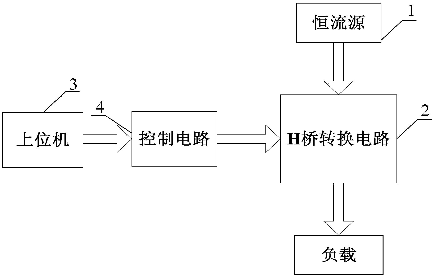
[0011] Specific implementation mode one: the following combination figure 1 Describe the present embodiment, the low-voltage high-current commutation device based on the H bridge described in the present embodiment, it includes a constant current source 1, an H bridge conversion circuit 2, a host computer 3 and a control circuit 4;
[0012] The positive pole of the constant current source 1 is connected to the positive pole of the H-bridge conversion circuit 2, the negative pole of the constant current source 1 is connected to the negative pole of the H-bridge conversion circuit 2, and one signal output terminal of the H-bridge conversion circuit 2 is connected to one end of the load, and the H-bridge conversion The other signal output end of circuit 2 is connected to the other end of the load;
[0013] The signal output terminal of the host computer 3 is connected to the signal input terminal of the control circuit 4 , and the signal output terminal of the control circuit 4 i...
specific Embodiment approach 2
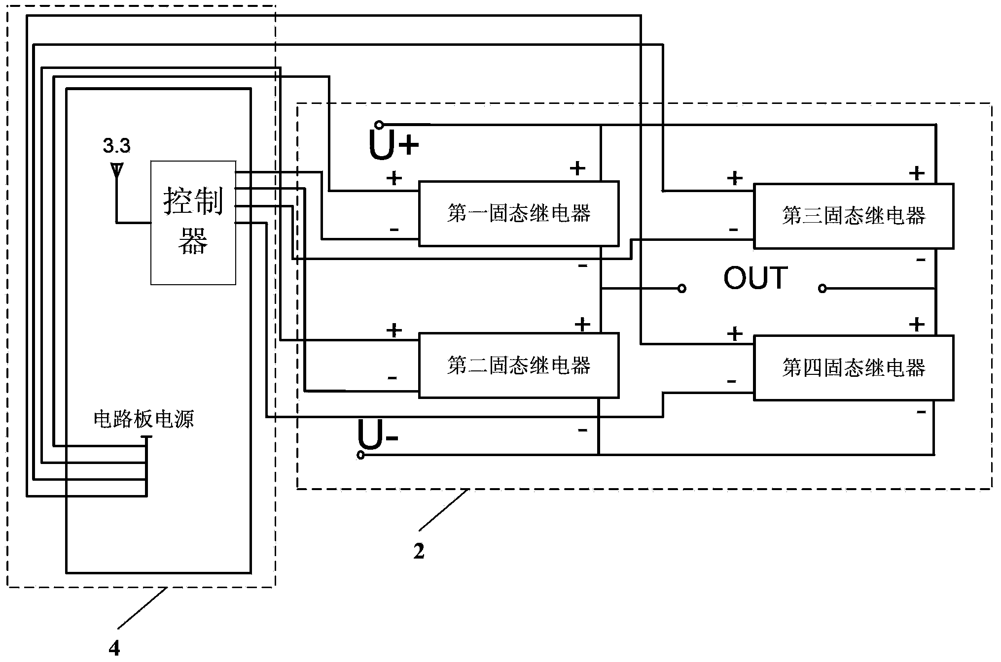
[0014] Specific implementation mode two: the following combination figure 2 Describe this embodiment, this embodiment further limits the low-voltage high-current commutation device based on the H-bridge described in the first embodiment, in this embodiment, the H-bridge conversion circuit 2 is composed of a first solid-state relay, a second solid-state relay , the third solid state relay and the fourth solid state relay;
[0015] The positive pole of the control power supply in the control circuit 4 is simultaneously connected to the positive pole of the first solid state relay control terminal, the positive pole of the second solid state relay control terminal, the positive pole of the third solid state relay control terminal and the positive pole of the fourth solid state relay control terminal, and the negative pole of the first solid state relay control terminal is connected The first H bridge control signal output terminal of the control circuit 4, the negative pole of t...
specific Embodiment approach 3
[0018] Embodiment 3: This embodiment is a further limitation of the H-bridge-based low-voltage and high-current commutation device described in Embodiment 1. In this embodiment, the output current of the constant current source 1 is greater than 0 and less than 1000A, and the output The voltage is greater than 0 and less than 1.5V.
PUM
 Abstract
Description
Claims
Application Information
 - Generate Ideas
- Intellectual Property
- Life Sciences
- Materials
- Tech Scout
- Unparalleled Data Quality
- Higher Quality Content
- 60% Fewer Hallucinations
Browse by: Latest US Patents, China's latest patents, Technical Efficacy Thesaurus, Application Domain, Technology Topic, Popular Technical Reports.
© 2025 PatSnap. All rights reserved.Legal|Privacy policy|Modern Slavery Act Transparency Statement|Sitemap|About US| Contact US: help@patsnap.com