A drive circuit for a source-controlled constant-current output power supply regulated by load voltage

A constant current output and drive circuit technology, applied in the direction of irreversible AC power input conversion to DC power output, etc., can solve the problem that individual differences of flyback transformers cannot be corrected, the accuracy and consistency of constant current control are difficult to guarantee, and the lack of load terminals Signal feedback and other issues to achieve the effect of improving relative consistency, expanding dynamic range, and ensuring independence

Active Publication Date: 2018-10-09
上海荧特微电子有限公司
View PDF6 Cites 0 Cited by
  • Summary
  • Abstract
  • Description
  • Claims
  • Application Information

AI Technical Summary

Problems solved by technology

However, due to the lack of signal feedback at the load end, the source-end current control is an open-loop control, which cannot correct the individual differences in the energy conversion of the flyback transformer, and the accuracy and consistency of the constant current control are difficult to guarantee.

Method used


Image

  • A drive circuit for a source-controlled constant-current output power supply regulated by load voltage
  • A drive circuit for a source-controlled constant-current output power supply regulated by load voltage
  • A drive circuit for a source-controlled constant-current output power supply regulated by load voltage

Examples


Embodiment Construction

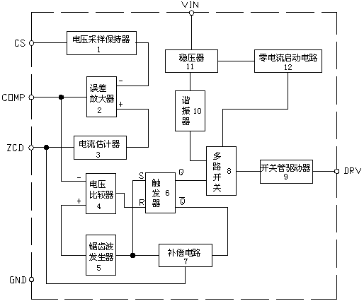
[0018] see Figure 2~3 , the present invention relates to a drive circuit for controlling a constant current output power supply at the source of load voltage regulation, the circuit includes a voltage sampler and holder 1, an error amplifier 2, a current estimator 3, a voltage comparator 4, and a sawtooth wave generator device 5, flip-flop 6, compensation circuit 7, multi-way switch 8, switch tube driver 9, resonator 10, voltage regulator 11 and start-up circuit 12, the voltage sample holder 1 will input the signal from the CS port of the chip Input the inverting input terminal of the error amplifier 2, the current estimator 3 inputs the signal input from the ZCD port of the chip to the non-inverting input terminal of the error amplifier 2, and the output terminal of the error amplifier 2 is connected to the COMP port of the chip, The signal input by the ZCD port of the chip is input to the compensation circuit 7, the output terminal of the compensation circuit 7 inputs the s...


PUM


Abstract

The invention relates to a source to a drive circuit, regulated by load voltage, of a source end controlling constant current output power. The circuit includes a voltage sampling holder (1), an error amplifier (2), a current estimator (3), a voltage comparator (4), a sawtooth generator (5), a trigger (6), a compensation circuit (7), a multi-way switch (8), a switch tube drive (9), a resonator (10), a voltage regulator (11) and a starting circuit (12). Through a mirroring voltage signal on an auxiliary winding, the drive circuit, regulated by the load voltage, of the source end controlling constant current output power corrects a source end current control signal and achieves closed-loop current control of a load current.

Description

technical field [0001] The invention relates to a power supply drive control circuit, in particular to a drive control circuit applied to a special power supply for LED lighting for source control and constant current output, and belongs to the electronic technical field of AC-DC power conversion. Background technique [0002] The driving system (chip) of the general-purpose single-stage power factor correction (PFC) flyback isolated AC-DC converter (power module) consists of five subsystems: self-power supply system, self-starting system, protection system, and power factor correction system And constant voltage constant current control system; such as figure 2 shown [0003] This power module has two most critical functions under the control of its drive system (chip): one is to realize the output controllable AC-DC energy conversion through the flyback transformer, and the other is to ensure the power factor during AC-DC energy conversion close to one. In addition to t...

Claims


Application Information

Patent Timeline
Patent Type & Authority Patents(China)
IPC IPC(8): H02M7/12
Inventor 张伟吴哲
Owner 上海荧特微电子有限公司
Why Eureka
Try Eureka