Metal part thermal forming two-man ladle mechanical arm

A technology of thermoforming and metal parts, applied in the direction of manipulators, program-controlled manipulators, manufacturing tools, etc., can solve the problems of cold insulation, slow casting speed, low safety, etc., and achieve easy-to-learn system operation, increase the speed of molten iron transportation, The effect of reducing personal safety hazards

Active Publication Date: 2013-12-04
浙江福瑞科流控机械有限公司
View PDF6 Cites 5 Cited by
  • Summary
  • Abstract
  • Description
  • Claims
  • Application Information

AI Technical Summary

Problems solved by technology

[0006] 1. The size (weight) of the pouring workpiece is limited, because the weight of one manual load is limited, and a casting ladle must be cast in a short time at one time. If the time is long, or two pots of molten iron are used for casting, the casting The workpieces that come out are prone to defects, delamination, cold insulation, and poor quality
[0007] 2. The labor intensity of the workers is high and the working environment is poor
[0008] 3. The safety factor is low, and if the force is not coordinated when lifting the ladle, the pouring ladle will roll over and cause burns and other industrial accidents; if the ladle is lifted by a vehicle, it is easy to cause industrial accidents such as "dumping the ladle" due to inertia during operation
[0009] 4. Low work efficiency, low productivity and low output
Low transportation speed, slow casting speed
[0010] 5. It is very dangerous to hoist with ordinary crane. The wire rope of the crane is soft, not rigid, and it is easy to be broken in high temperature. Moreover, the ladle on the iron hook of the wire rope seems to be swinging on a swing when the truck is running.
And it needs a worker to operate the crane, and the stop position of the crane is not accurate, it takes a long time to adjust the driving position, and the ladle shakes back and forth during the adjustment process, the time is long and the safety is low

Method used


Image

  • Metal part thermal forming two-man ladle mechanical arm
  • Metal part thermal forming two-man ladle mechanical arm

Examples


Embodiment 1

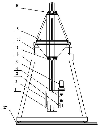
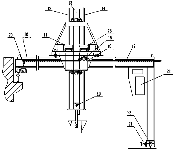
[0032] Embodiment 1, a kind of manipulator for ladle carrying by thermoforming of metal parts, comprises mechanical arm, program-controlled box 24 and gantry 6, and mechanical arm is installed on gantry 6, and program-controlled box 24 is fixed on the side wing of gantry 6, and mechanical arm and program-controlled Case 24 is electrically connected, and moving guide rail 22 is set below gantry 6, and gantry 6 is also provided with gantry moving left servo motor 20, gantry moving right servo motor 21, gantry pulley 23, and there are two pairs of gantry pulleys 23 here, A pair of installation positions are on the top, and the other pair is on the bottom. The gantry pulley 23 can slide on the moving guide rail 22, so that the gantry 6 moves left and right along the moving guide rail 22, and the positions of the cabinet 8 and the ladle 1 are adjusted.

[0033] The mechanical arm includes a ladle lifting mechanism, a ladle horizontal rotation mechanism, a ladle vertical rotation mec...


PUM


Abstract

The invention relates to a metal part thermal forming two-man ladle mechanical arm which comprises the mechanical arm, a program control cabinet and a portal frame. The mechanical arm is mounted on the portal frame, the program control cabinet is fastened to a side wing of the portal frame, the mechanical arm is electrically connected with the program control cabinet, and the mechanical arm comprises a casting ladle lifting transportation mechanism, a casting ladle horizontal plane swing mechanism, a casting ladle vertical plane swing mechanism, a positioning mechanism and a temperature measurement mechanism. The mechanisms act on the casting ladle to achieve movements such as lifting transportation, rotation, positioning, casting and reciprocating loading and transportation. According to the metal part thermal forming two-man ladle mechanical arm, the PLC microcomputer technology controls the movements of the parts, the sequence of the movements, the time and relative angles of the movements, work efficiency is high, and the operation is safe.

Description

[0001] technical field [0002] The patent of the present invention relates to an intelligent manipulator used in the process of metal smelting and forming to lift and carry ladles to realize casting mechanization. Intelligent pouring equipment for packing, lifting, rotating, positioning, pouring, reciprocating shipment and other actions. Background technique [0003] At present, the molten iron in the foundry industry is carried by workers, that is, three or four young and strong workers. Each worker holds two iron rods in his hand. The jin ladle walks sideways; after arriving at the casting site, three or four people cooperate with each other to tilt the ladle and pour the molten iron into the sprue of the workpiece. [0004] Or it can be hoisted by ordinary crane, and the ladle can be moved to the casting site by moving the crane in three directions, and then the workers can turn the worm wheel on the ladle to tilt the ladle and pour the molten iron into the sprue of the...

Claims


Application Information

Patent Timeline
Patent Type & Authority Applications(China)
IPC IPC(8): B25J9/00
Inventor 高飞郑建军李国华李泽玉邵一忠李福邦陈理续伟华
Owner 浙江福瑞科流控机械有限公司
Why Eureka
Try Eureka