Plywood type front edge structure of flying machine

An aircraft and leading edge technology, which is applied in the field of the leading edge structure of the aircraft, can solve the problems of uneven temperature distribution in the spanwise direction of the leading edge surface, affecting the effect of structural dredging and heat protection, and low system reliability, and achieves simple structure and reliability. High, small size effect

Inactive Publication Date: 2013-12-04
NAT UNIV OF DEFENSE TECH
View PDF5 Cites 11 Cited by
  • Summary
  • Abstract
  • Description
  • Claims
  • Application Information

AI Technical Summary

Problems solved by technology

That is to say, the existing mode is to bend the conventional metal heat pipe into the front-edge configuration and embed it into the front-edge structure to exert its high thermal conductivity, but such a structure is relatively complicated, and the reliability of the system is low. The spanwise temperature distribution of the edge surface is not uniform, and the contact problem between the heat pipe wall and the aircraft surface seriously affects the structure's dredging and heat protection effect

Method used


Image

  • Plywood type front edge structure of flying machine
  • Plywood type front edge structure of flying machine
  • Plywood type front edge structure of flying machine

Examples


Embodiment Construction

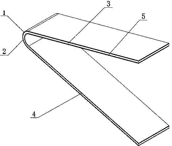
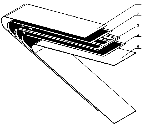
[0021] Such as figure 1 , figure 2 Shown, a kind of laminate type leading edge structure of aircraft, this leading edge structure comprises outer layer skin plate 1, inner layer cladding plate 5, is located between the outer layer skin plate 1 and the inner layer cladding plate 5 for supply The flow channel combination plate for the circulating flow of heat-conducting working medium; the flow channel combination plate is formed by stacking the outer layer capillary channel plate 2, the middle layer flow channel plate 3 and the inner layer capillary channel plate 4 in order from outside to inside, that is The leading edge structure of the entire aircraft is composed of outer skin plate 1, outer capillary channel plate 2, middle layer channel plate 3, inner capillary channel plate 4 and inner cladding plate 5 in order from outside to inside. Pressed and welded by diffusion welding.

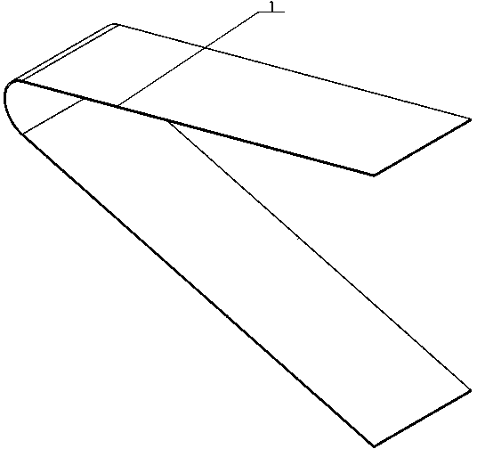
[0022] Such as image 3 As shown, the outer skin panel 1 is a whole panel whose panel shape ...


PUM


Abstract

The invention relates to a plywood type front edge structure of a flying machine, which can be particularly applied to the front edge of a nose cone or an aerofoil of a flying machine performing high-Mach flight, and comprises an outer layer stressed-skin diaphragm, an inner layer cladding plate and a flow pass combined plate arranged between the outer layer stressed-skin diaphragm and the inner layer cladding plate and used for circular flow of heat conduction working medium. According to the plywood type front edge structure, the structure similar to a heat pipe is formed by utilizing etching of layer plates and overlying, and the layer plates are connected through diffusion welding as per the shape of the front edge so as to form the integrated front edge structure of the flying machine, and the front edge structure has the advantages of simple structure, low investment, small size and high stability.

Description

technical field [0001] The invention relates to a leading edge structure of an aircraft, in particular, it can be used for a nose cone or a leading edge of a wing of an aircraft flying at a high Mach number. Background technique [0002] When the aircraft is flying at a high Mach number, it will face serious thermal barrier problems, especially the leading edge components. When the flight altitude is 24km, the flight speed reaches Mach 7, and the heat flux density on the leading edge nose cone with a radius of 20mm is as high as 2~3MW / m 2 , the wall temperature is as high as 1400K. When the flight altitude is 25km, the flight speed reaches Mach 6, and the heat flux density on the leading edge nose cone with a radius of only 1~2mm is as high as 4~5MW / m 2 , the wall temperature is as high as 1600~1900K, and when the flight altitude is 20~100km, the flight speed is 10~20 Mach, and the heat flux on the leading edge nose cone with a radius of 10~30mm is as high as 10MW / m 2 , ...

Claims


Application Information

Patent Timeline
Patent Type & Authority Applications(China)
IPC IPC(8): B64C1/12
Inventor 刘伟强孙健聂涛刘洪鹏张峰谢伦娅
Owner NAT UNIV OF DEFENSE TECH
Why Eureka
Try Eureka